wave input. Notice that the
trace
starts
near the midpoint of the
waveform. Pig. 288 shows the
same
signal with the TRIGGER
LEVEL control turned towards the "+" marking. Notice that
the
trace
starts
at
a higher amplitude on the signal. Fig.
28C
shows that the waveform
starts
at
a lower point when the
TRIGGER LEVEL control
is
turned towards the
"-"
marking.
information. The TRIGGER POLARITY switch must be set to
the "+., position
if
the sync pulses
are
positive (pointing
up»)
or
to the
"-"
position
if
they
are
negative. Selecting the wrong
polarity may result
in
an
unstable trace, and will always give
incorrect peak·to-peak readings when the Delta peak-to-peak
function
of
the digital readout is used.
Special
trlg"",lng
conditIons
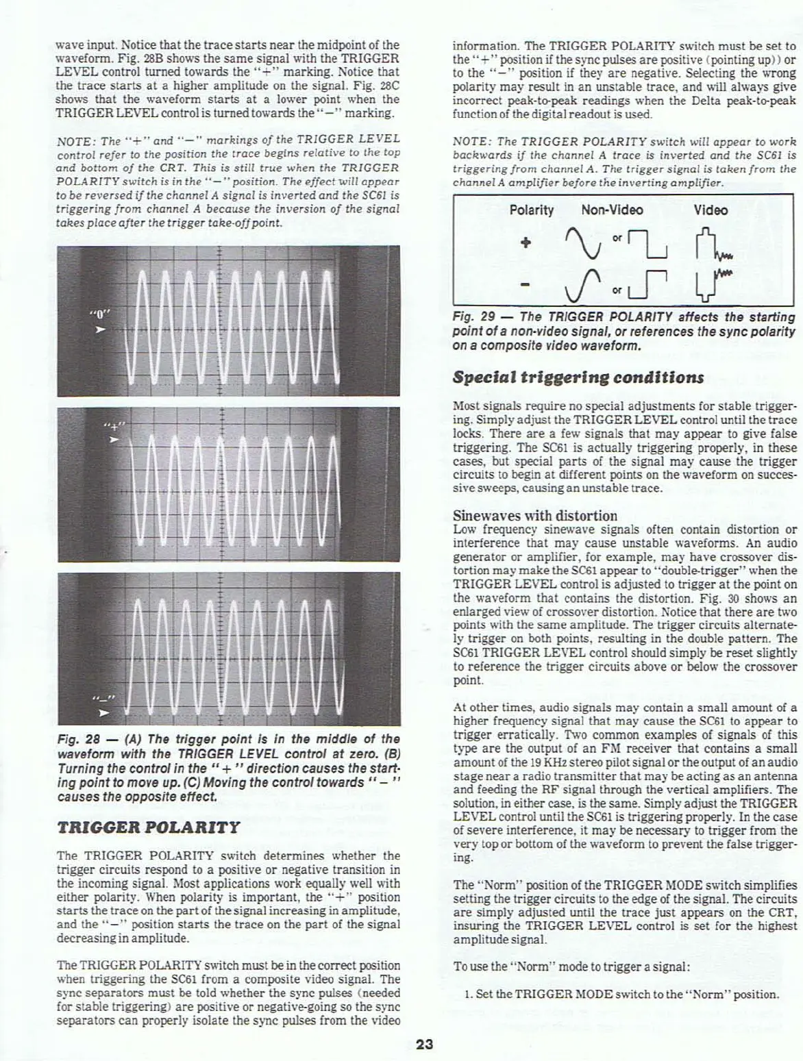
Fig. 29 -
The
TRIGGER
POLARITY affects the starling
point
of
a non-video Signal, or references the sync pofarity
on
a composite video waveform.
VideoNon-VideoPolarity
The
"Norm"
position
of
the TRIGGER
MODE
s>witch
simplifies
setting the trigger circuits
to
the edge
of
the signal. The circuits
are
simply adjusted until the trace just appears
on
the CRT.
insuring the TRIGGER LEVEL control
is
set for the highest
amplitudesignal.
NOTE:
The
TRIGGER
POLARITY
switch
will
appeor
to
work
bockwards
if
the
channel
A !roce is
inverted
ond
the
SC61
is
triggering
from
channel
A.
The
trigger signal is
taken
from
Ihe
chClnnel
A
amplifier
before
the
inverting
amplifier.
Sinewaves with distortion
Lo
.....
frequency sinev.'ave signals often contain distortion or
interference that may cause unstable waveforms.
An
audio
generator or amplifier. for example, may have crossover dis-
tortion may make the
SCSI
appear to "double-trigger" when the
TRIGGER LEVEL control is adjusted to trigger at the point
on
the wa\'eform that contains the distortion. Fig.
30
sho
.....
s an
enlarged view
of
crossover distortion. Notice that there
are
two
points with the
same
amplitude. The trigger circuits alternate-
ly trigger
on
both points, resulting
in
the double pattern. The
SC61
TRIGGER LEVEL control should simply
be
reset slightly
to
reference the trigger circuits
atM:we
or below the crossover
point.
Most signals require
no
special adjustments for stable trigger-
ing. Simply adjust theTRIGGER LEVEL control until the trace
locks. There
are
a
fe
.....
signals that may appear
to
give false
triggering. The
SCSI
is actuaUy triggering properly.
in
these
cases, but special parts of the signal may cause the trigger
circuits
to
begin
at
different points on the wa\'eform on succes-
sh'es
.....
eeps, causing an unstable trace.
At
other times, audio signals may contain a small amount
of
a
higher frequency signal that may cause the
SCSI
to appear to
trigger erratically. Two common examples
of
signals
of
this
type
are
the output
of
an
FM receiver that contains a small
amount
of
the
19
KHz stereo pilot signal or the output of
an
audio
stageneara radio transmitter that may be acting as
an
antenna
and feeding the
RF
signal through the vertical amplifiers. The
solution,
in
either case, is the same. Simply adjust the TRIGGER
LEVEL control until the
SCSi
is
triggering properly. In the
case
of
severe interference, it may be necessary to trigger from the
very top or bottom of the waveform to prevent the false trigger-
ing.
Fig. 28 - (A)
The
trigger
point
Is
In the middle of the
waveform with the
TRIGGER
LEVEL
control
at
zero.
(8)
Turning the control in the
If
+
II
direction causes the starl-
ing point
to
move up. (C) Moving the control
towards"
-
..
causes the opposite effect.
TRIGGER POLARITY
The TRIGGER POLARITY sv.itch determines whether the
trigger circuits respond
to
a positive or negative transition
in
the incoming signal. Most applications work equaUy well with
either polarity.
When
polarity is important, the
"+"
position
starts
the trace
on
the
part
of
the signal increasing
in
amplitude,
and the
"-"
position
starts
the trace on the part of the signal
decreasingin amplitude.
NOTE:
The
"+"ond
"-"
morkings
of
the
TRIGGER
LEVEL
control
refer
to
the position Ihe troce begins re/otive 10 the
top
C1nd
bottom
of
the CRT. This is
still
true
when the
TRIGGER
POLARITY
switch
is
in the
"-"
position. The
effect
will
oppear
to
be
reversed
if
the
chonnel
A signal is
inverted
ond
the 5C61 is
triggering
from
chClnnel A becCluse
the
inversion
of
the signol
tokes
ploce
ofter
the trigger
toke·offpoint.
The TRIGGER
POL<\R.ITY
switch must be
in
the correct position
when triggering the
SC61
from a composite video signal. The
sync separators must
be
told whether the sync pulses (needed
for
stable triggering)
are
positive or negative-going so the sync
separators can properly isolate the sync pulses from the video
To
use the
"Norm"
mode to trigger asignal:
1. Set the TRIGGER
MODE
s
....
itch
to the
"Norm"
position.
23