6.
Press
the "VECJ'OR" display pushbutton.
7. Adjust Ihe azimuth adjustment
scre\lo'
until the "'ector pat·
tern
is
asclose
as
possible to a straighlline
~;th
zero phase shift
(045-
angle) as
sho'A'll
in Fig.
12.
The playback head is
now
adjusted for optimum performance.
Appl1ling
sigJUlls
to
the
vertical
inputs
Signals may be supplied to the
$C61
in
se\'era! ways.
Each
method has certain advantages and disadvantages thai should
beconsidered beforemakinga connection.
To
adjust the
~rd
head on a three-head machine:
1. Perform the alignment
of
the playback head listedabove.
2. RemO\'e the alignment tape from the machine and load a
blank tape.
3.
Apply a I KHzsinewave
to
both the left and right inputs. Use
a
..
y"
connector so the same signal
is
applied
to
both channels
with no phaseshift.
04.
Adjusl the recording level controls until both recording
VU
meters
are
sho'Aing 0
dB
le\·els.
5.
Placethe machine
in
the "record" mode.
6.
Set the "source/tape" switch to the
"tape"
position to
monitor the recorded signal from the tape using the pla)'back
head.
7.
Depress
the"A
& B" display pushbutton theSC61.
8. Adjust the record azimuth adjustment screw until the signal
played back has the highest possible amplitude.
NOTE:
There
will
be
a
delay
of
abollt
S7
second
bel
....
·eell
the
time
Ihe sigllQl
is
recorded
by
Ihe
record
heod
and
picbd
lip
by
the
pla)'bacolt
head
.'fake
the
adjllslmellt
and
then
wait
for
the
pettern
on
the
SC61
to
stabili:e
befare
maltin,
addiliollQl adjllst·
ments.
]96%8]
IOU>eapaclt31
probes
Most measurements require the
use
of
the supplied
39G183low-
capacity probes. The probes isolate the capacity
of
the test
leads,
CRT
input circuits. and
DC
input circuits from the circuit
being tested, reducing the chances
of
circuit loading and
measuring errors. The special design
of
the
39G183
probes
protects the
SC61
to
3000
volts
DC
or
AC
peak·to-peak, allowing
measurements in high \'oltage circuits. The
39G183
probes also
pro\'ide
a
separate
isolated
circuit
for
DC
\!altage
measurements.
Reducecl sensiti\ity is the only disad\'antage
of
using the low·
capacity probes. The probes divide
the
amplitude of all signals
by
ten before reaching the
SC61
mput jacks. The probes
aJlov.-
measurement of signals
as
small as
25
millivolts
LQ?..5
\·olls).
which is adequate
for
most circuit tests.
Both the CRT display and digital tests read direct \\;th the
39G183
probes. Keep this
in
mind
if
you
use
competitive scopes
that require multiplying
by
ten for the low--eapacity probes.
You
do
not
need to multiply readings
by
ten
.....
hen using the
SC61
with
lOX
probes.
A special resistance wire between the probe and connector
prevents waveform distortion caused
by
signal renections
inside the coaxial cable. Do
not
replace this
...
.-ire
with an)' other
t:,.-pe,
as
.....
a\
dorm
distoMion
will
occur. The tiny center conduc·
tor requires special connection techniques. Send de.fecth·e
probes to the $encore Service Department
if
sen.ice is e\'er
required.
9.
Press
the
""ECTOR"
displa)' pushbutton
on
the
SC61
and
adjust
the
record head azimuth adjustment until the \'ector pat·
tern
is
as
close
as
possible to a straight line
'Aith
zero phaseshift
(045-
angle) as shown
in
Fig.
12.
The recording head
is
now
properly set. The recording azimuth
adjustment has been rererenced
to
the standard alignment tape
since the playback head was set to this standard before the
recording head was adjusted.
A special high temperature co\'ering protects the resistance
\\ire from heat damage. such
as
contact \\;th a soldering iron.
Both ends ha\'e extensive strain relief to protect the cable from
damagedUring normal use. The
39G183
probes willgi\'e years
of
reliable use with reaSOnable care. A\'oid excessive mechanical
stresses
on
the special cable. Keep the probes out
of
the way of
hea\'y objects and off the
Ooor
.....
hen
not
in
use, or breakage of
the probe tipor body
is
possible.
Using
the
SC6%
with
sweep
generators
or
curve
tracers
The
special
design
of
the
39Gl83
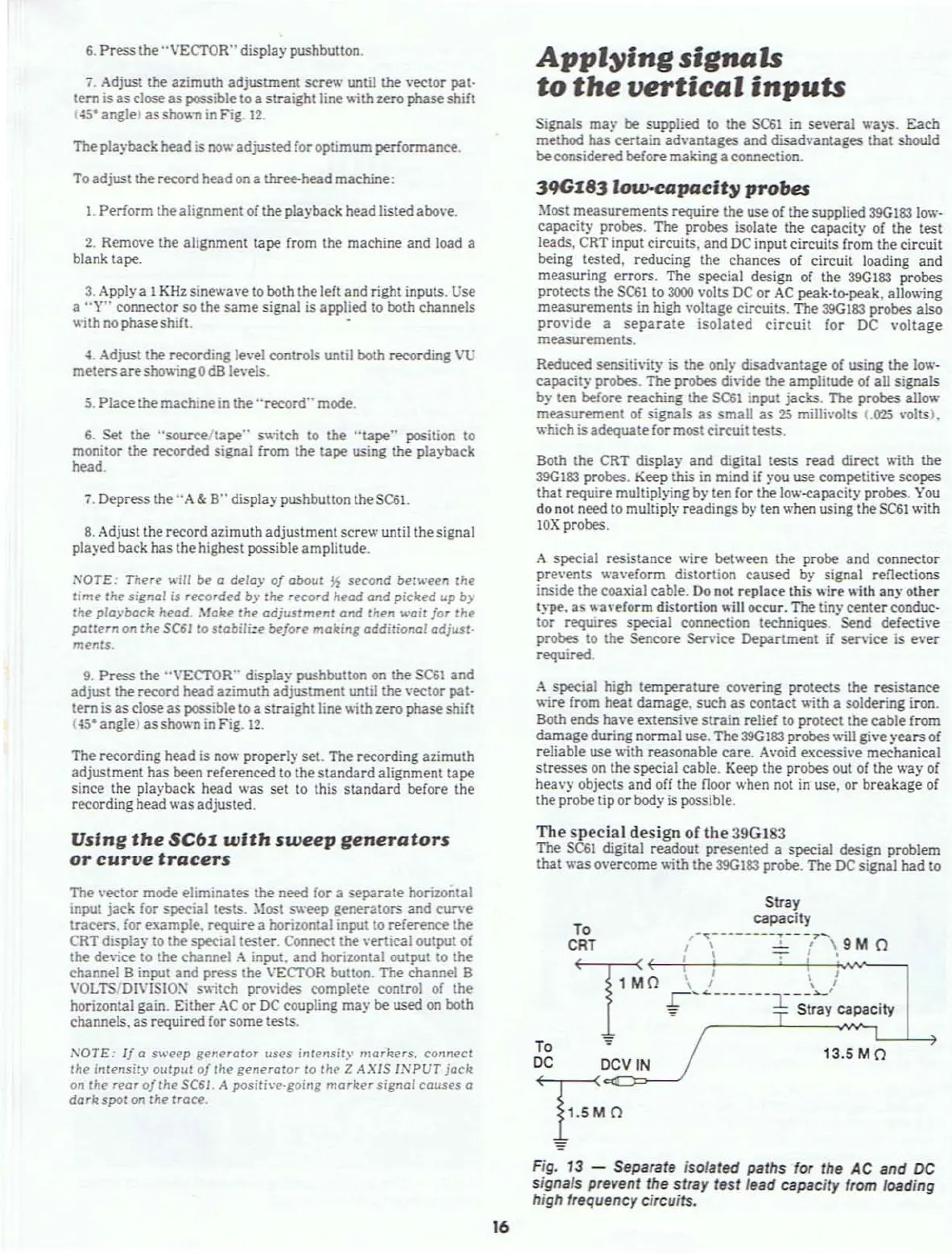
The
SC61
digital readout presented a special design problem
that was overcome \\ith the
39G183
probe.
The
DC
signal had to
13.5 M 0
To
Stray
capacity
...
- - - -
---
-
..
- -
-7
....
CRT
/\
.....!....{\9MO
~o
;_L
~-~'-,;
I
-:::
Stray capacity
To
';"
DC
DCV
IN
Fo
The vector mode eliminates the need for a separate horizontal
input jack for special tests. :\lost sweep generators and curve
tracers.
for
example. require a horizontal input
to
reference the
CRT
display to the special tester. Connect the \'ertical output
of
the de,,;ce
to
the channel A input. and horizontal output to the
channel B input and press the
\'EcrOR
button. The channel B
VOL
TS'OIVISIOX switch provides complete control
or
the
horizontal gain. Either
AC
or
DC
coupling may be
used
on both
channels.
as
required for some tests.
NOTE:
If
a
sweep
generator
lIS('S
inl('nsil)'
markers.
conneCl
Ihe
inlensit)'
OUlPll1
of
lhe
generator
10
lhe
Z
AXIS
INPUT
jecit
on
the
rear
a/the
SC61
A
posith·e·going
marlter
signal
cOllses a
darRspol
on
the
trace.
Fig,
13
- Separate isolated paths for the
AC
and
DC
signals prevent the stray test lead capacity from loading
high frequency circuits.
16