cations requiring the absolute
DC
\'alue of
part
of
a
.....
aveform
(such
as
the amplitude of the highs and
low's
of
a digital signa))
mJUire
conventional analog technique. as explained on page21.
lbe
DCV
function is fully autoranged. allo
....
ing
it to operate
independentl~'
of the CRT display. The CRT display
may
be
adjusted to
an~'
con'·enient size. and the
l~-PlIT
COUPLING
sv.itch may be
in
anyposition \\;thout affecting the
DC
readings.
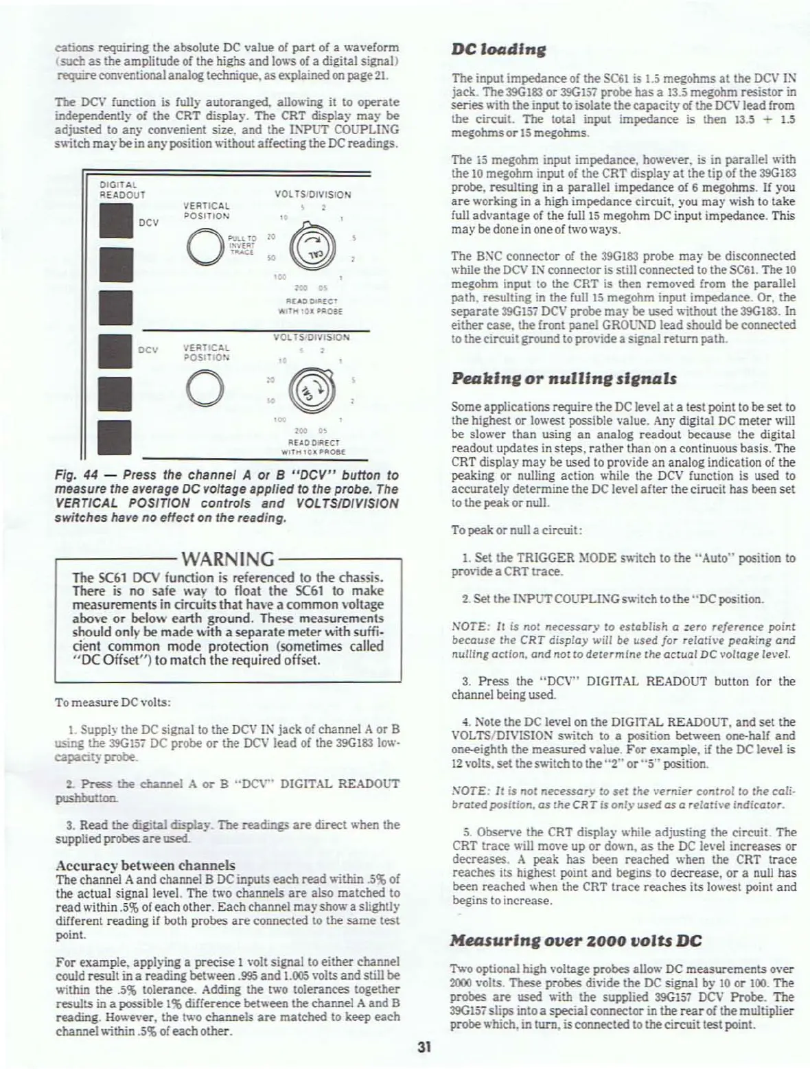
Fig. 44 - Press the channei A or 8
"DeV"
buHon to
measure the average
DC
voltage applied to the probe.
The
VERTICAL POSiTION controls
and
VOLTS/DIVISION
switches
have no effect
on
the reading.
P""ldnl/
or
nulllni/
s11/'"'1s
The
is megohm input impedanCf:.
hov,.'e\·er.
is
in
parallel with
the
10
megohm input
of
the CRT display at the tip of the 39G183
probe. resulting
in
a parallel impedanCf: of 6 megohms.
If
you
are
working
in
a high impedance circuit.
)'00
may wish to take
full advantage of the full
15
megohm
DC
input impedance, This
may
be done
in
one of two ways.
DC
I_dlnl/
To peakor null a circuit:
The input impedance
of
the
SC61
is
1.5 megohms
at
the
DC\'
IN
jack. Tbe39G183 or
39G157
probe has a
13.5
megohm resistor
in
series \\ith the input to isolate the capacity
of
the
DCV
leadfrom
the circuit.
The
total input impedanCf:
is
then 13.5 -
1.5
megohms
or
15
megohms.
Someapplications
require the
DC
level
at
a test point to be set to
the highest or
lowest possible value.
Any
digital
DC
meter will
be slo
.....
er
than using an analog readout because the digital
readout updates
in
steps, rather than on a continuous basis, The
CRT display
may be used to provide an analog indication
of
the
peaking or nulling action while the
DCV
function is used to
accurately determine the
DC
le\'el
after
the cirucit has been set
to the peak or null.
The
Bi"\C
connector of the
390183
probe rna)· be disconnected
.....
hile the
DCV
IN ('{)nnector is still connected to the
SC61.
The
10
megohm input to the CRT
is
then remo\·ed from the parallel
path. resulting
in
the full
15
megohm input impedance. Or. the
separate
39G157
DCV
probe:
ma,y
be used without the
39G183.
In
either case. the front panel
GROU~l)
lead should be connected
to thecircuit ground to
pro\ide
a signal return path.
-
.-
IlHOOIR[Cf
WI'H'O~PROB[
IlU,OOlll[Cf
'#Ii
II<
'0'
....
Oll
.,
VOL
TS'OIVISION
,
:
"©)
,:
VERTICAL
POSITION
OIGITAl
REAOOuT
.DC'
•
•
•
D
-C-
..
-------~,'"O;;'.,',.';;D;;;"~""'D;;N,---
• VERTIC'='l
~
~OSITIO':
,~
• 0
:(@
•
,...-----
WARNING
------,
The
SC61
DCV
function
is
referenced to
the
chassis.
There
is
no safe way to float the
SC61
to make
measurements
in
circuits that
hne
a common voltage
above
or
~ow
earth ground. These measurements
should only be made with a separate meter \\1th suffi-
cient common mode protection (sometimes called
"DC
Offset
U
)
to match the required offset.
1.
set
the TRIGGER :\lODE s\\itch to the "Auto" position to
providea CRT
trace.
2.
set
the Il\-PUT COUPLING sv.itch to the
..
DC
position.
NOTE:
It
fs
not
necessor)'
to estoblish 0
:ero
reference point
becouse the
CRT
disp/o)' will be used for relativE'
pE'al!:ing
and
nulling action.
ond
not
to
determine
the
actual
DC
voltage level.
To measure
DC
volts:
1
Suppl~·
the
DC
signal to the
DC\'
IN
jack of channel A or B
using
the
39G157
DC
probe or the
00'
lead of the
39G183
low-
eapa.Cl~·
probe.
2..
Press
the
channel A
or
B
"DC\'"
DIGITAL READOliT
_too.
3.
Press the "OCV" DIGITAL READOUT button
for
the
channel being
used.
4.
Note the
DC
level
on
the DIGITAL READOUT. and set the
VOL
TS/DIVISION s\\itch to a position between one-hall and
one-eighth the measured value. For example.
if
the
DC
le\'el
is
12
\·olts. set the switch to the
"2"
or
"5"
position.
;-;OTE:
II
is
nOI
necessar),
to
set
the
vernier
control to
the
coli·
brated
position.
as
theCR T is onl)' used
as
0
reloti~'e
indicotor.
3.
Read the digital display.
The
readings
are
direct when the
supplied
probes
are
used..
Accuracy
between channels
The channel Aand channel B
DC
inputs each read \\;thin
.5%
or
the actual signal le\'el. The
two channels
are
also matched to
read
within
.5%
of each other. Eachchannel may
show
a slightly
different reading
if
both probes
are
connected
to
the
same
test
point.
For example. applying a precise 1
volt signal to either channel
could result
in
a reading betv;een
.995
and
UI05
volts and still be
\\ithin the
.5%
tolerance. Adding the two tolerances together
results in a possible
1%
dilferenCf: between the channel A and B
reading. Howe\·er. the
two
channels
are
matched to keep each
channel
\\ithin
.5%
of each other.
5.
Observe the CRT display while adjusting the circuit. The
CRT
It'ace
\\i11
move
up
or
d0'4"tl.
as
the
DC
le\'el increases or
decreases. A peak has been reached when the CRT
traCf:
reaches its highest point and begins to decrease. or a null has
been reached when the CRT trace reaches its lowest point and
begins to increase.
Me4Uurlnl/
Ol!e1'
2000
volts
DC
T
.....
o optional high "oltage probes allow
DC
measurements over
2000
volts. These probes divide the
DC
signal by
10
or 100. The
probes
are
used
\\;th
the supplied
39G157
DCV
Probe. The
39G157
slips into a special connector in the
rear
of the multiplier
probe:
which.
in
tum,
is
connected to the circuit test point.
31