circuits in the sync
separators
that isolate the two vertical inter-
laeed
fields
to
prevent overlap of
the
signals from the first
and
second fields.
The
signals
are
displayed by setting
the
TIMEBASE-FREQ
switch
to
the
.1
m sec position, the
trigger
mode to --TV".
and
expanding the waveform ten times. The special sync
separators
result in a
stable
trace.
To view the VITSor VIRS:
1.
Set the
nJ\IEBASE·FREQ
S"1ritch
to
the.l
m sec position.
2.
Set
the
TRIGGER
~IODE
sv.itc:h to
the
"TV" position and
adjust
the
other trigger adjustments for a properly locked signal.
3.
Center the VIRS
or
VITS signal
on
thehorizontal
center
line.
4.
Activate the
lOX
expand mode by pulling the HORIZ
POSITION
control.
5_
Center
the
desiredsignal on the CRT.
,\'OTE:
The VIRS
or
VITS
signals
are
present
lor
only
one
line
out
0/
the
525
lines
0/
video
in/ormation.
Any
oscilloscope
shows
a
greal
reduclion
in CRT
inlensily
when viewing
signals
....
·ith
duty C)'cles Ihis low. You
may
need
to
turn
the
INTENSITY
contral/ully
clockwise to view
the
signal.
Some
competitive
oscilloscopes
may
appear
brighter
than
the
SC61
when viewing
these signals, but this
is
usually because
they
do not ha\'e Ihe
speciol circuits
Ihat
eliminate the
overlap
between
the
IWO
verticaljiefds.
The
result
is
a trace
that
appear.s twice
as
bright.
but has t
...
'O
....
·al:eforms wilh a half-line
shlft
super-imposed
on
each other.
Chroma Reference
Black
Reference
Burst
1
144
---
19th
lIne-----.!~
Sync Pulse
Fig. 36 -
The
VJRS
consists
of
a chrome reference, a
luminance reference, and a black reference.
Fig.
37 - Increase the INTENSITY control setting
to
view
the
VJTS
and
VJRS
on the expanded signal.
27
MeASuring
time
with
the
TlMEBASE.FREQ
switch
The digital Delta TIme function eliminates
analog
time measure-
ments for most applications. A
ft!\l.·
applications. however,
may
require
theuseof the CRT because the
time
period is too short to
accurately
set
the DELTA BEGIN and DELTA END controls.
There
are
two
sets
of
markings
around
the TIMEBASE-FREQ
s
....
'itch. Use the inside numbers to
measure
time. The
numbers
represents the amount of
time
needed for the
trace
to mo
...
e
horizontall}'
one
major
division on the CRTscreen. The horizon-
tal
..
-ernier control must
be
set
to
the
fully
c1ock
.....
ise
"Cal"
position for
accurate
results.
To
measure
the
time
periodofany signal:
1.
Set the horizontal
vernier
to
the fully clockwise
"Cal"
position.
2.
Adjust the
TI)iEBASE·FREQ
s
....
'itc:h until sufficient detail
is sho
.....
n on
the
CRT to
..
'it!\l.,
the
part
of the
.....
a
..
·efonn
to
be
measured.
Use
th!'!
lOX
expand
feature.
if
necessary.
on
fast
signals.
3. Adjust the VERTICAL POSITION control until the
part
of
the
.....
a
...
eform to be analyzed is
on
the center horizontal graticu1e
line.
4_
Adjust the HORIZ POSITIOS control until the beginning of
the
part
of
the
.....
a
...
eform to
be
analyzed is lined up
....
ith
a verti·
cal
CRTgraticule
line (it does not matter....-hichone).
5.
Count the
number
of
di
..
isions
occupied
by
the
part
of the
.....a
...
eform that must be
measured.
Remember
that each minor
division represents .2
major
divisions.
6.
Multiply the number of divisions times the setting or the
Tl~IEBASE-FREQ
s
....
itch.
The s
.....
eep
rate
is one-tenth the
marked
time
if the
lOX
expand feature is used.
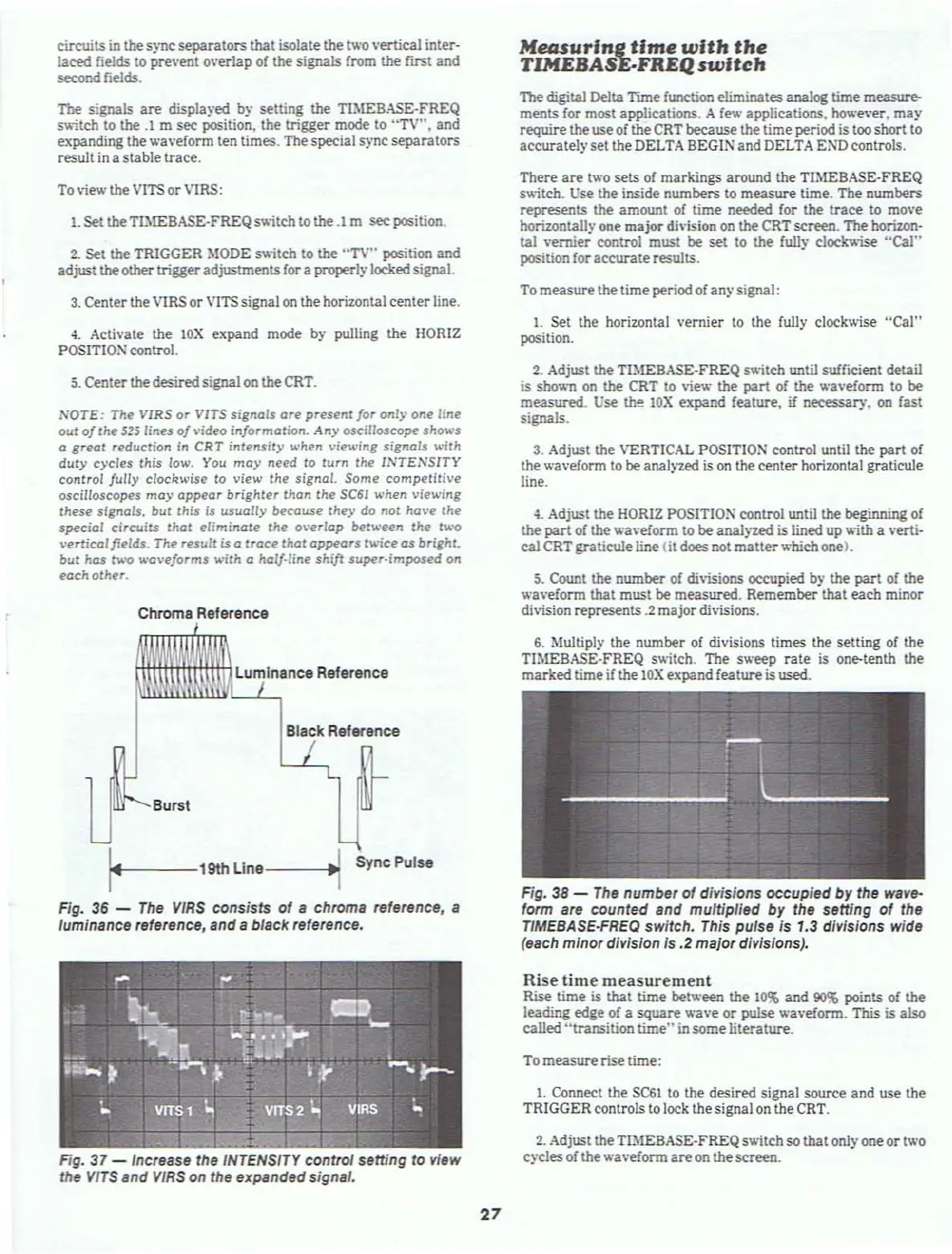
Fig.
38
-
The
number
of
divisions occupied by the wave-
form are counted and multiplied by the setting
of
the
TIMEBASE·FREQ switch. This putse
is
1.3 divisions wide
(each minor division is
.2
major divisions).
Rise time measurement
Rise time is
that
time
bet een the
10%
and
90$
points of the
leading
edge of a
square
a
...
e
or
pulse
.....
a
...
eform. This is also
called
"transition
time"
in
some
literature.
To
measure
rise time:
1. Connect the SC6l to the desired signal source
and
use the
TRIGGER controls to lock the signal
on
the CRT.
2.
Adjust the TlMEBASE-FREQ switch
so
that
onlyone
or
two
cycles
of the
.....
a
...
eform
are
on the
screen.