Inverting
the
channel
A
trace
for
special
tests
Some waveforms
are
easier
10
interpret
if
im'erted, One example
is using the dual-trace mode of the
SC61
for
comparing
the input
and output of
an
inverting
stage
to
determine
if
the
stage
is
adding distortion
or
phase
shift to
the
signal, The channel A
trace
may
be inverted by pulling the channel A VERTICAL
POSITION control
to
the
"oul"
position. The in\'ersion circuit
affe-cts
only the displayed waveform. This is
important
.....
he-n
the
A channel signal is used to
trigger
the
horizontal circuits. The
triggering polarity of the inverted signal will not
change
when
channel A
is inverted, allowing
the
triggering circuits to
be
set
one
time
while
the
channel
A.
trace
is
alternately
displayed
as
an
inverted
or
non·invertedsignal.
NOTE:
Be
sure
the
inversion
switch
is
set
to the
non·inverting
mod€.'
wh€.'n
making
standard
m€.'asurements. Confusion in
waveform
interpretation
may
result
if
the
channel
A
trace
is
unintentionally
inverted.
Algebraic
addition
or
subtraction
of
signals
(A+B
or
JJ.A)
Some applications require two signals to be
added
to form a
composite signal
or
subtracted
to
display the difference of two
signals. The
SC61
will add
the
two signals
(A+B)
when both
the
CHAN
Aand
CHAN
B display pushbuttons
are
depressed
at
the
same
time. Subtraction occurs when both buttons
are
pressed
and
the
channel A signal is inverted by pulling
the
channel A
VERTICAL
POSlTto~
control.
Remember
that
the phase relationships of the two
signals
will
determine
whether the two signals
actually
increase
when
added
or
cancel when
subtracted.
If
both
signals
are
of
the
same
phase. for example. adding
the
signals will
cause
the
size of
the
displayed waveform to increase. Subtracting two signals of
the
same
phase
will
cause
a
decrease
in the sizeof the display wave-
form
or
total cancellation. But. if
the
two signals
are
ISO"
out of
phase.
the
opposite will occur. Adding out-of·phase signals
results in cancellation, and
subtracting
causes
an
increase
in
waveform size. Any
phase
shift besides
0"
and
ISO"
will result in
the instantaneous
sum
or
difference of the signals
to
be displayed.
Locating amplifier distortion
The
"A
+
B"
and
"B
-
A"
display modes
may
be used
to
isolate
audio
amplifier
stages
that
are
causing distortion. The
SC61
is
connected to
the
input
and
output of a single
stage
and
then set to
cancel
the
output signal with
the
input signal. The resulting
display is the distortion
added
by
the
tested
stage.
The audio
signal
source
used should be a
sine
wave, but does not need to
have
extremely
low distortion le\tels because
any
distortion in
the
test signal will be present
at
the output of
the
stage
being
tested, resulting in cancellation of
the
signal
source
distortion. It
is possible
to
isoiatedistortion
as
small
as
.1% using this method
because
the
gain of
the
SCSI
channels
may
be
increased
beyond
the
level that
.....
ould
cause
full-scale denection,
if
channel A and
B
were
displayed normally, while
the
residual distortion
part
of
the
signal will
remain
relatively small on
the
CRT display.
To display the distortion produced
by a single
stage:
1.
Connect
an
audio oscillator to
the
amplifier
input.
2.
Connect
the
channel A probe to
the
input of
the
stage
to
be
tested. and
the
channel B probe to
the
stage
OUlpUt.
3.
set
the
VOLTSIDIVISIO~
switch for both channels to pro-
ducea
full·scalesignal.
4.
Confirm that the phase of
the
channel B signal is opposite
13
that of
the
channel A signal.
If
they
are
the
same
phase, pull the
channel A VERTICAL
POSITIO~
control to invert channel
A.
5. Depress the
CHAN
A and
CHAN
B display pushbuttons
at
lhesame
time to produce
an
"A
+
B"
display.
6.
Adjust the
VERNIER
control of
either
channel until
the
trace
is
as
small
as
possible vertically. This
step
balances
the
amplitude of
the
two
traces
for full cancellation of
the
input
signal. The resulting signal, that
cannot
be eliminated
\\ith
this
step. is
the
distortion added by
the
channel being tested.
7.
If the result of
step6
is a
straight
line,
there
is less than
2%
distortion in the
measured
signal. The distortion resolution
may
be
increased
by ten
times
(20 dB) b)' increasing thesensitivit)' or
both VOLTSIDIVISION s
.....
itches by ten times.
IJ.
for example.
channel A
is
set
to 1 volt
per
division.
and
channel B is
set
ror 2
volts
per
division.
change
them
to.
I
and
.2
respectivel)'.
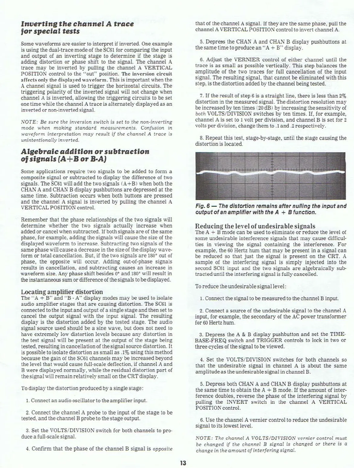
8.
Repeat this test, stage-by-stage. until the
stage
causing
the
distortion is located.
Fig. 6 -
The
distortion remains aHe, nulling the
input
and
output
of
an amplifier with the A + B function.
Reducing
the
level
or
undesirable
signals
The A + B mode
can
be used to
eliminate
or
reduce the level of
some
undesirable
interference
signals that
may
cause
difficul-
ties in \'ie
.....
ing
the
signal containing
the
interference.
For
example, the
60
Hertz
hwn
that
may
be present in a signal
can
be
reduced so
that
just
the
signal is present on the CRT. A
sample
of the interfering signal is simply injected into
the
second
SC61
input and
the
t
.....
o signals
are
algebraically
sub-
tracted
until the interfering signal is fully cancelled.
To reduce the undesirable signal
level:
I.
Connect
the
signal to
be
measured
to
the
channel B input.
2.
Connect a
source
of
the
undesirable signal
to
the
channel A
input, for example, the
secondary
of
the
AC
power
transformer
for
60
Hertz hum.
3.
Depress
the
A & B display pushbutton
and
set
the
TIME-
BASE-FREQ s
.....
itch and
TRIGGER
controls
to
lock in two
or
three
cyclesof
the
signal to
be
vie
.....
ed.
4.
Set
the
VOL
TS/DIVISION s
.....
itches for both channels so
that
the
undesirable signal in channel A is about
the
same
amplitude
as
the
undesirable signal in channel
B.
5.
Depress both
CHA.~
A
and
CHAN B display pushbuttons
at
the
same
time
to obtain the A + B mode.
If
the
amount
of inter-
ference doubles,
reverse
the
phase
of
the
interfering signal
by
pUlling
the
INVERT s
.....
itch in the channel A VERTICAL
POSITION control.
6.
Use the channel A vernier control to reduce
the
undesirable
signal toits lowest level.
NOTE:
The
channel
A
VOLTS/DIVISION
vernier
control
must
be
changed
if
Ihe chann€.'l B signal is
changed
or
there
is a
change
in
the
amount
of
interfering
signal.