ADN Digital Conference System | 63
Configuring the conference system via the central unit
Displaying the type and number of the connected conference units – “Units“
The “Units” menu item displays the number of all delegate units (“D1”) and chair-
person units (“C1”) used in the conference system (“System”).
You can view how many conference units are connected to the PORT I (“CU.I”) and
II (“CU.II”) sockets of the ADN CU1 central unit. If you are using at least one ADN PS,
the number of conference units connected to the central unit (“CU”) and per power
supply (e.g. “PS01”) is displayed.
Number of conference units marked
with an asterisk“*“
If the number of conference units is marked with an asterisk“*”, the conference
system cannot determine the exact number of conference units and their connec-
tion to a specific ADN PS power supply. This happens when the topology has been
changed (e.g. when conference units have been added to the conference system
during operation).
To make the conference system determine the exact number of conference units
and their connection to a specific ADN PS and to make the asterisk “*“ disappear:
왘 Perform a manual self-test (see page 67)
Or:
왘 Switch the conference system on again (see page 41).
Displaying the topologies connected to the ADN PS power supplies– “Topology“
The “Topology” displays – for all ADN PS power supplies used in the conference
system – the connected topologies (simple cabling with cable strings or redundant
ring topology).
In the case of simple cabling, the outputs 1 and 2 of the respective PORT socket are
displayed (e.g. “PS01.I.1” for ADN PS power supply connected to the central unit at
the first position, PORT I, output 1). In the case of redundant ring topology, only
PORT I or II is displayed ( e.g. “PS01.I”).
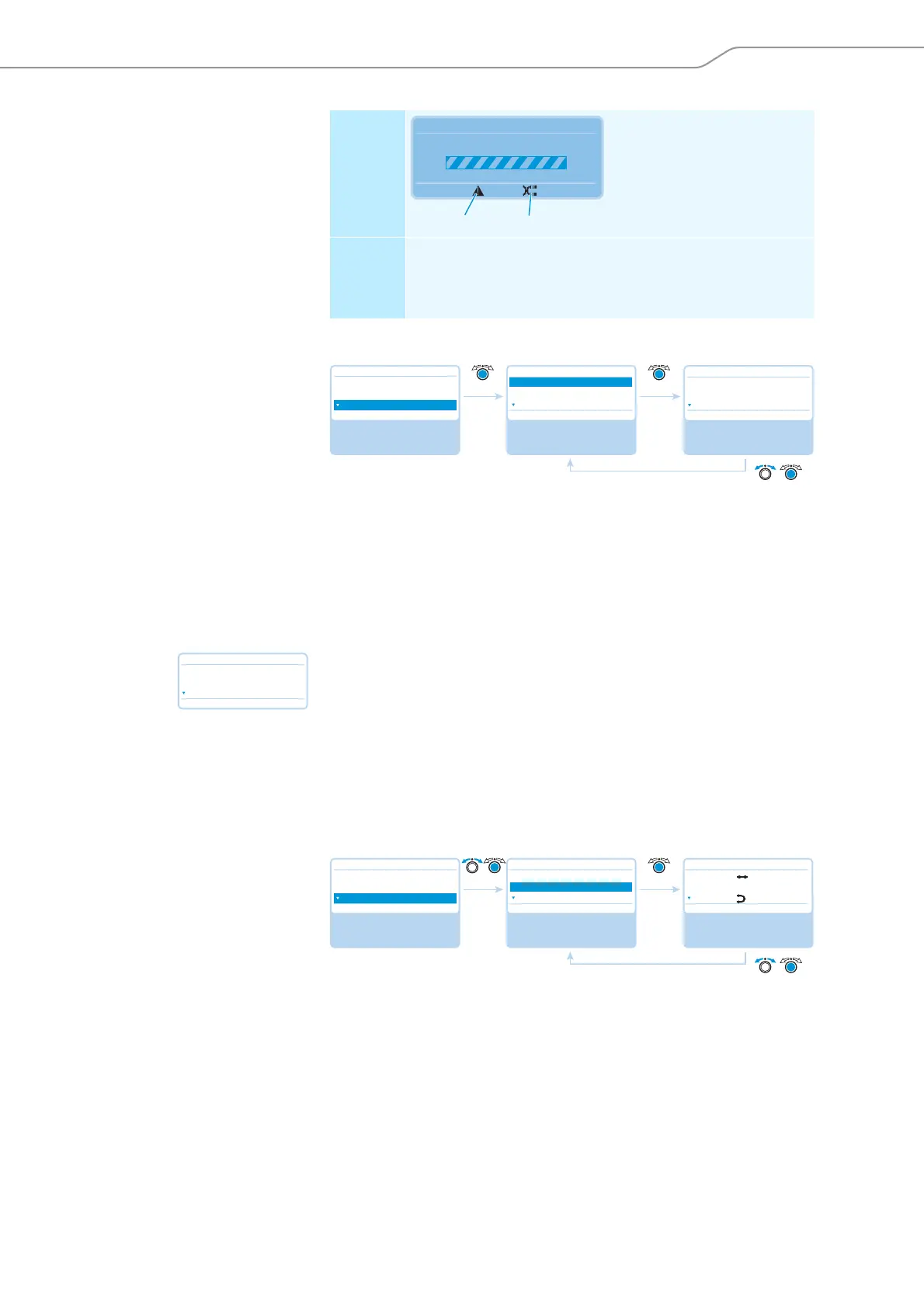
Display Only possible if the conference
units are directly connected to
the ADN CU1 central unit:
The warning triangle and the
cable fault icon are displayed
and the “Processing...” bar
appears.
Error and
remedy
The IN socket and the OUT socket on a conference unit have
been accidentally swapped; the microphone LED and the signal
light ring of the affected conference unit flash red.
왘 Check if the cables are connected correctly (see page 30).
Processing ...
Audio Distribution Network
N
L
Main Menu
Conference Menu
Audio Menu
System Menu
System Menu
Units
Topology
Diagnostics
No
Select and call up the
“System Menu”
submenu
Select and call up the
“Units” menu item
View the information;
exit the menu item
Units
No
System : 216 D1 06 C1
CU : 00 D1 04 C1
PS01 : 29 D1 01 C1
Units
No
System : * 216 D1 * 06 C1
CU : * 00 D1 * 04 C1
PS01 : * 29 D1 * 01 C1
Main Menu
Conference Menu
Audio Menu
System Menu
System Menu
Units
Topology
Diagnostics
No
Select and call up the
“System Menu”
submenu
Select and call up the
“Topology” menu item
View the information;
exit the menu item
Topology
No
PS01.I.1 :
PS01.I.2 : – –
PS01.II :