2.13
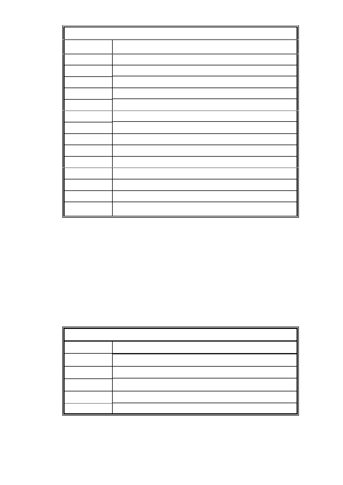
Table 2.4 Signal terminal location PL5
Terminal Function
1 Analogue input 1 +ve
2 Analogue input 1 -ve
3 Analogue input 2 +ve
4 Analogue input 2 -ve
5 Not used
6 Not used
7 Analogue input 2 valid
80 V
9 Analogue input 1 valid
10 0 V
11 0 V
12 Auto calibration initiate
13 0 V
14 Range change
2.7 Serial output connection
The serial data output is provided via the 9 pin ’D’ type connector located on the rear
of the instrument ( PL6 ) conforming to the EIA RS-232C interface specification. The
connections for the RS232 output are shown in table 2.5. For compliance with EMC
standards, connections to PL6 must be made using a screened cable, not exceeding
3 metres in length. The screen is terminated at the EMI shielded ’backshell’ or
conductive cover, of the ’D’ type connector. For unidirectional serial data output only
pins 3, 5 and 8 are used. Pin 8 is only used if hardware handshaking using DTR ( data
terminal ready ) is enabled. In DTR mode the instrument will wait until CTS ( pin 8 )
becomes active. At this point an output data set will be transmitted via pin 3. See
section 5.9 for details on configuring the serial output port.
Table 2.5 Serial output connections PL6
Terminal Function
2 Received data (RXD)
3 Transmitted data (TXD)
5 Signal common/ground
7 Request to send (RTS)
8 Clear to send (CTS)