2.14
2.8 External autocalibration connection
For analysers configured with the external autocalibration option, an additional output
connector, PL 8, is fitted into the sample gland plate ( see figure 2.10 ). This connector
supplies two pairs of relay contacts which may be used to control external valves.
These relay contacts are rated at 1.0 A, 264 V AC and 1.0 A, 30 V DC ( non-inductive
). Screened cable should be used to connect to solenoid valves of length not exceeding
3m with the screen terminated at the instrument end. It will be necessary to fit a
suppression device across the coils of the solenoid valves. For DC supplies a diode is
recommended. For AC supplies a 0.047uF capacitor in series with a 100
S resistor
would generally be found satisfactory.
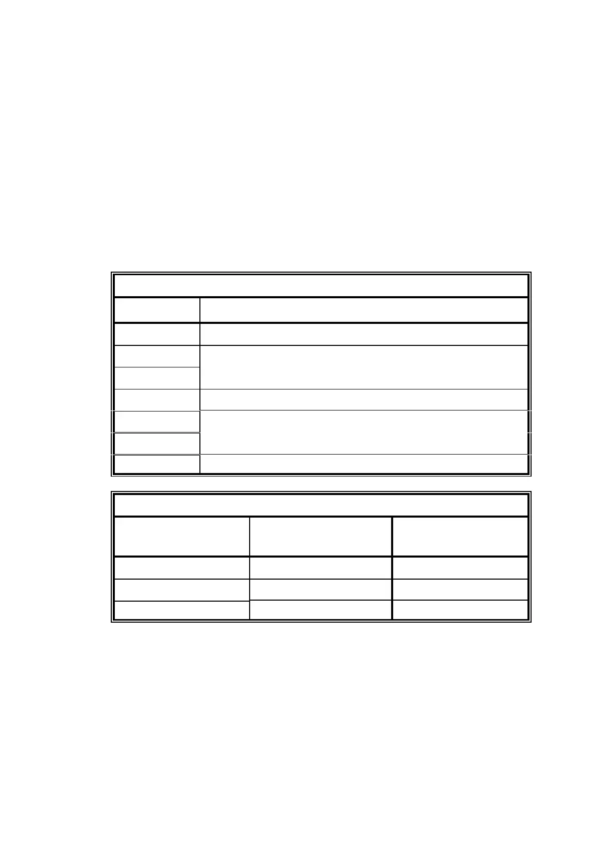
Table 2.6 contains the connector pin out details. Table 2.7 contains the truth table
showing the relay contact conditions for sample gas, calibration gas 1 and calibration
gas 2.
Table 2.6 External autocalibration connections
Terminal Function
1 Ground.
2 Relay contacts for valve 1.
Sample / Calibration selection.
3
4 Not Used
5 Relay contacts for valve 2.
Cal. Gas 1 / Cal. Gas 2 selection.
6
7 Ground.
Table 2.7 External autocalibration truth table
Gas Required Relay Contacts for
Valve 1
Relay Contacts for
Valve 2
Sample gas OPEN OPEN
Calibration gas 1 CLOSED OPEN
Calibration gas 2 CLOSED CLOSED