2.18
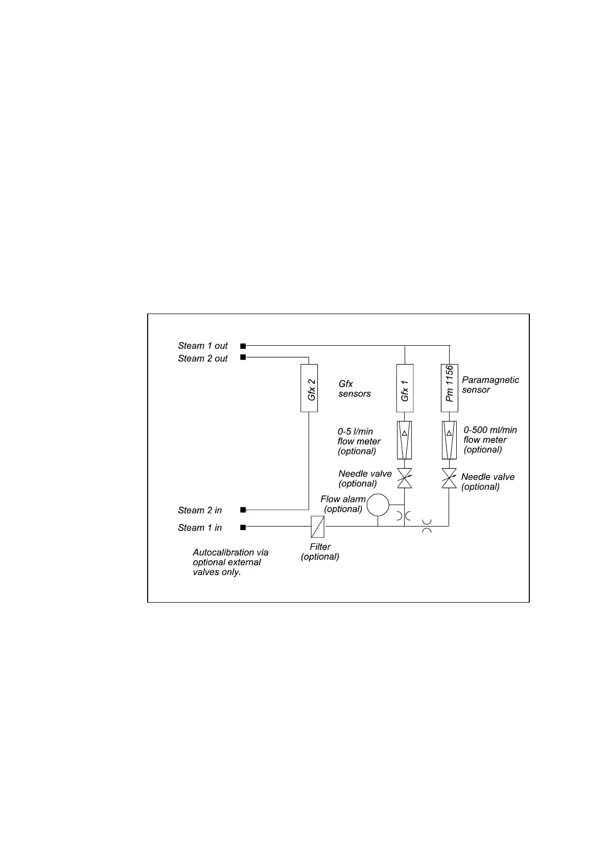
Figure 2.12 Typical dual stream, dual Gfx configuration
gas passes through the first transducer then passes into the second transducer. The
paramagnetic transducer is connected in parallel with the Gfx transducers.
An orifice restrictor is connected in series with the paramagnetic transducer to limit the
sample flow rate through the transducer. This restrictor will produce approximately 250
ml/min flow through the paramagnetic transducer for an inlet pressure of 5 psig.
A number of optional sampling components are available with the single stream
configuration analyser. These include needle valves to regulate the flow through the
Gfx transducers. The flow through the Gfx transducers should not exceed 2.0 l/min.
If the optional needle valves are not used then external provision to limit the sample
flow to 2.0 l/min should be provided.
The single stream analyser configuration may be used with either internal or external
calibration valves.
Dual gas stream configuration
Figure 2.12 contains a typical flow diagram for dual stream configuration analysers.
The dual stream configuration is only used in the 4904 analyser when two Gfx
transducers are fitted. Here the two Gfx transducers are connected to two separate
sample streams with different inlets and outlets. If a paramagnetic transducer is
supplied then this will be connected in parallel with the first Gfx transducer.
An orifice restrictor is connected in series with the paramagnetic transducer to limit the
sample flow rate through the transducer. This restrictor will produce approximately 250
ml/min flow through the paramagnetic transducer for an inlet pressure of 5 psig.
A number of optional sampling components are available with the dual stream