5.3
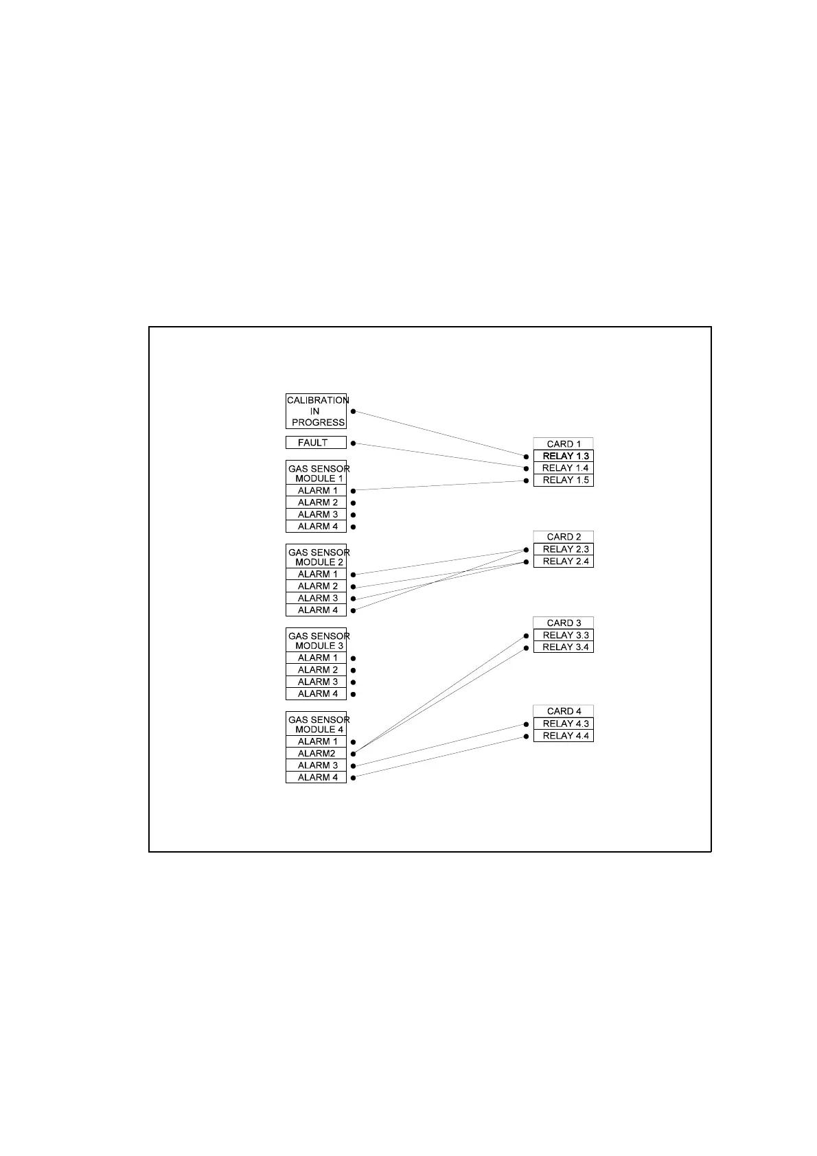
Figure 5.1 Allocation of relays
5.2 Allocation of relays
Each relay is set up by selecting the conditions under which it is to operate. Each relay
may be set up to respond to any combination of the following :-
i) Fault
ii) Calibration in progress
iii) Any number of alarms
See Table 5.2 for procedure.
Any existing relay allocation may be edited or cleared. See Table 5.3 for relay
assignment clearing procedure.
Figure 5.1 illustrates the allocation of relays to analyser conditions. Any condition
(individual alarm, fault or calibration in progress) may ’tied’ to any relay or number of
relays ie any number of links may be made between the analyser conditions on the left
hand side and the relays on the right hand side.

 Loading...

