: Feb. 9 2004
1
AR-M550/M620/M700 SIMULATION 8 - 49
Operation/Procedure
Press [START] key, and the adjustment is automatically performed.
When the adjustment is completed, the adjustment result is displayed.
If the adjustment is not completed normally, "ERROR" is displayed.
When an error occurs, the adjustment result is not revised.
Operation/Procedure
1) Enter the target density level in the image density correction with
10-key.
2) Press [START] key.
Operation/Procedure
1) Select the number corresponding to the setting mode with 10-key.
2) Press [START] key.
3) Enter the set value.
4) Press [START] key.
Operation/Procedure
44-2
Purpose Adjustment
Function
(Purpose)
Used to perform the gain adjustment (image density
sensor LED current adjustment) of the image density
sensor and the gain adjustment (OPC drum marking
sensor LED current adjustment) of the OPC drum
marking sensor.
Section Image process (Photoconductor)
Item Operation
DMLED Drum marking sensor gain adjustment
PCLED Image density sensor gain adjustment value
DRUM Kind of the drum
0 = Other
1 = SHARP drum
The gain adjustment is completed. Press [CUSTOM SETTINGS] key.
44-4
Purpose Setting
Function
(Purpose)
Used to set the target density level in the image
density correction.
Section Image process (Photoconductor/Developing)
Item Operation
Press [START] key. Press [CUSTOM SETTINGS] key.
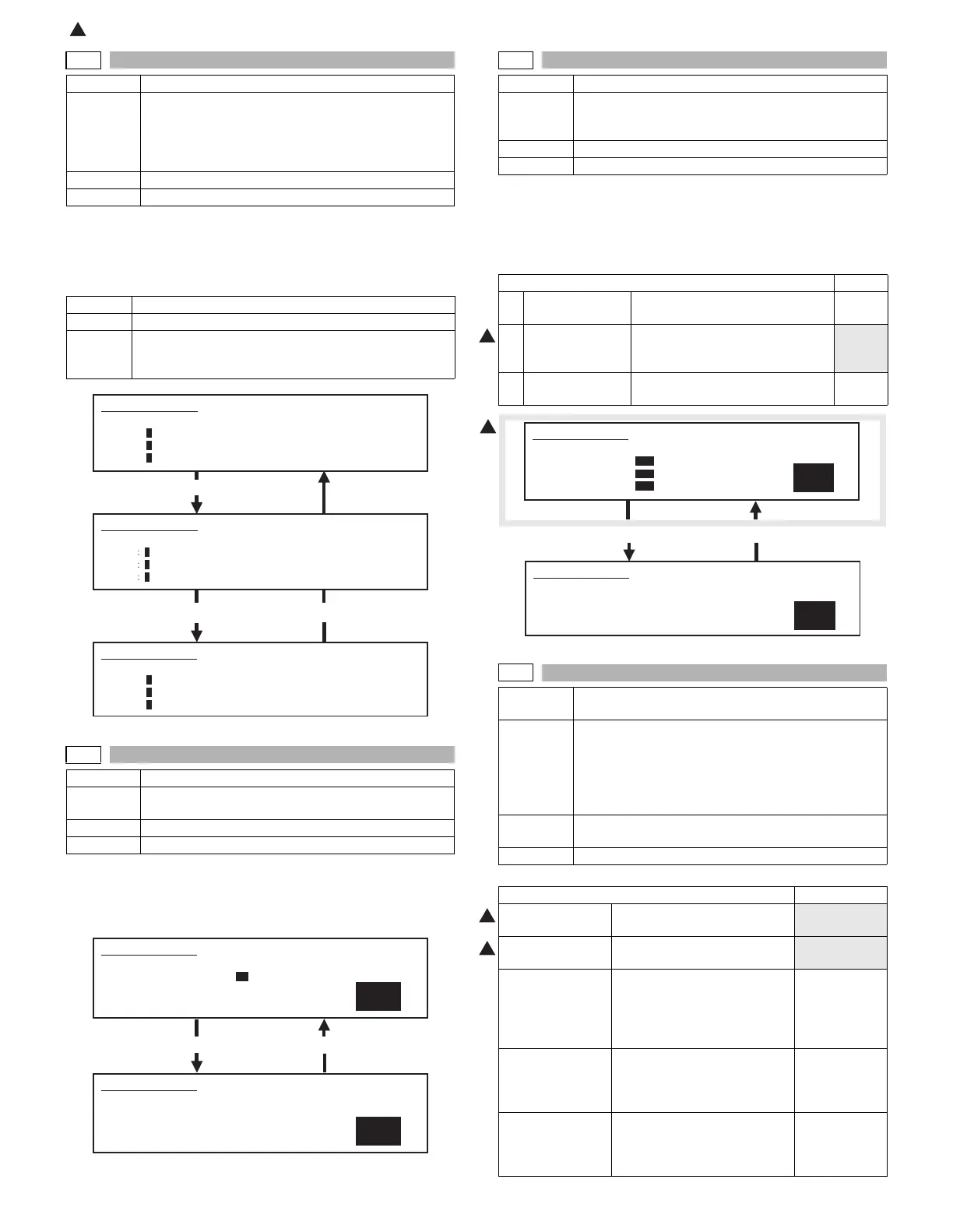
SIMULATION 44-2
PROCON GAIN ADJUSTMENT. PRESS START.
DMLED: 0
PCLED: 0
DRUM : 0
SIMULATION 44-2
PROCON GAIN ADJUSTMENT. EXECUTING
...
DMLED
0
PCLED
0
DRUM
1
Press [START] key.
SIMULATION 44-2
PROCON GAIN ADJUSTMENT. COMPLETE.
DMLED: 0
PCLED: 0
DRUM : 1
SIMULATION 44-4
1
PROCON INITIAL DENSITY SETUP. PRESS START.
1.PROCON INI DENSITY 32
SIMULATION 44-4
PROCON INITIAL DENSITY SETUP. INPUT VALUE 0-255, AND
PRESS START.
1.PROCON INI DENSITY
32
44-5
Purpose Setting
Function
(Purpose)
Used to set the reference developing bias voltage, the
reference main charger grid voltage, and the laser
power in the image density correction.
Section Image process (Photoconductor/Developing)
Item Operation
Item Default
1 GRID BIAS VOL Main charger voltage for
developing bias voltage correction
350
2 DEVE BIAS VOL Reference developing bias voltage
for developing bias voltage
correction
150
3 LASER POWER Reference laser power for
developing bias voltage correction
50
Press [START] key. Press [CUSTOM SETTINGS] key.
44-9
Purpose Adjustment/Setup/Operation data output/Check
(Display/Print)
Function
(Purpose)
Used to check the data related to the image forming
section correction (process correction) result
(corrected main charger grid voltage, the developing
bias voltage, and the laser power voltage in each print
mode). (This simulation allows to check that correction
is performed normally or not.)
Section Image process (Photoconductor/Developing/Transfer/
Cleaning)
Item Data Operation data (Machine condition)
Item NOTE
DRUM
ROTATION TIME
OPC drum rotation time (sec)
Reset by SIM
24-11.
DEVE MIXING
TIME
Developing roller rotation time
(sec)
Reset by SIM
24-11.
DRUM OPC drum identification code 1: For AR620/
550/625/555
0: For other
than AR620/
550/625/555
GR BS Actual main charger grid
voltage (including correction) /
Main charger grid voltage
adjusted with SIM 8-2
DV BS Actual developing bias voltage
(including correction) /
Developing bias voltage
adjusted with SIM 8-1
1
1
SIMULATION 44-5
1
PROCESS CONTROL TEST. SELECT 1-6, AND PRESS START.
1.GRID BIAS VOL 350
2.DEVE BIAS VOL 150
3.LASER POWER 50
SIMULATION 44-5
PROCESS CONTROL TEST. INPUT VALUE 0-, AND PRESS START.
1.GRID BIAS VOL
350
1
1
 Loading...