: Feb. 9 2004
1
AR-M550/M620/M700 SIMULATION 8 - 48
4) Press [START] key.
Operation/Procedure
1) Select the number corresponding to the adjustment item with 10-
key.
2) Press [START] key.
3) Enter the setting (adjustment) value with 10-key.
4) Press [START] key.
Unless special measures are required, do not change the setting val-
ues below.
Operation/Procedure
2) Press [START] key.
NOTE: Set to 222.
When bit=1, correction is made.
NOTE: BIT0 is not displayed, but set to the developing bias correction
function.
This setting is forcibly made enable, and cannot be disabled.
Item Japan
Inch
series
AB
series
1INSIDE
NORMAL
Fusing roller inside/
normal mode
185 200 205
2 OUTSIDE
NORMAL
Fusing roller outside/
normal mode
185 200 205
3INSIDE
PREHEAT
Fusing roller inside/
preheat mode
140 170 170
4 OUTSIDE
PREHEAT
Fusing roller outside/
preheat mode
140 170 170
5LEFT
NORMAL
Sub-heat roller/
normal mode
185 200 205
6LEFT
PREHEAT
Sub-heat roller/
preheat mode
140 170 170
Press [START] key. Press [CUSTOM SETTINGS] key.
43-3
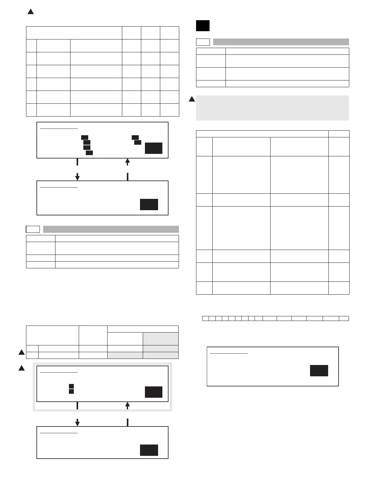
Purpose Setting (Adjustment)
Function
(Purpose)
Fusing roller RPM setting.
Section Fixing (Fusing)
Item Operation
Item Set range
Default
AR-M550N/U,
AR-M620N/U
AR-M700N/U
1NORMAL 0 – 99 36
35
2SLOWDOWN 0 – 99
46 44
Press [START] key. Press [CUSTOM SETTINGS] key.
SIMULATION 43-1
1
FUSER TEMPERATURE SET. SELECT 1-6, AND PRESS START.
1. INSIDE NORMAL 200 5. LEFT NORMAL 200
2. OUTSIDE NORMAL 200 6. LEFT PREHEAT 170
3. INSIDE PREHEAT 170
4. OUTSIDE PREHEAT 170
SIMULATION 43-1
FUSER TEMPERATURE SET. INPUT VALUE, AND PRESS START.
1. INSIDE NORMAL
200
1
1
SIMULATION 43-3
1
FUSER MOTOR SPEED SETTING. SELECT 1-2, AND PRESS
START.
1. NORMAL 36
2. SLOWDOWN 46
SIMULATION 43-3
FUSER MOTOR SPEED SETTING. INPUT VALUE, AND PRESS
START.
1. NORMAL
36
44
44-1
Purpose Setting
Function
(Purpose)
Used to set enable/disable of correction operations in
the image forming (process) section.
Section Image process (Photoconductor/Developing/Transfer/
Cleaning)
Item Operation
1) Each bit (7 kinds) is assigned to each correction item to set
ENABLE/DISABLE of the operation.
Each bit is assigned with 0 or 1 value. Enter the total values of
items which are desired to be valid with the 10-key.
Item Default
BIT1 OPC drum membrane
decrease (sensitivity/
potential) correction
Laser power/main
charger grid voltage
1
BIT2 The range of the toner
patch making voltage in
the developing bias
voltage/main charger
grid voltage correction is
specified. (Voltage limit)
Developing bias/main
grid voltage (adjusted by
SIM 8-1 and 8-2) ±100v
1
BIT3 For humidity correction Toner concentration
correction
1
BIT4 Toner concentration
correction
When the developing
bias/main charger grid
voltage correction is
changed more than the
specified level, the toner
concentration control
level is corrected.
1
BIT5 Toner concentration
correction B
Correction for the
developer life
0
BIT6 Toner concentration
correction C
Toner concentration
correction in low density
image continuous print
1
BIT7 OPC drum for
environment correction
1
Bit151413121110 9 8 7 6 5 4 3 2 1
00000000EnvTcon_CTcon_B Tcon_A Humidity Pcon_lm Drum
1
SIMULATION 44-1
PROCESS CORRECTION VALUE SETTING. INPUT VALUE 0-999
AND PRESS START.
BIT1: DRUM
BIT2: PROCON_LM BIT3: HUMIDITY
BIT4: TONERCON_A BIT5: TONERCON_B
BIT6: TONERCON_C BIT7: ENVIRONMENT
223
 Loading...