1
I
I Li
II
1
1
1
II
1
1
-
1
I
I
I
6 ADJUSTMENT/REPLACEMENT OF EACH PART
MUX-100 SERVICE MANUAL 6 - 35
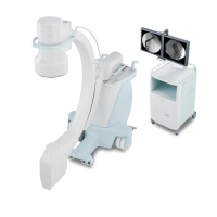
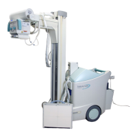
8. Put a label on respective connectors of two new DC motors. (Refer to
the wiring diagram shown in Fig. 6-54 (c).)
(a) (b)
(c)
Fig. 6-54 Label on Connectors of DC motor
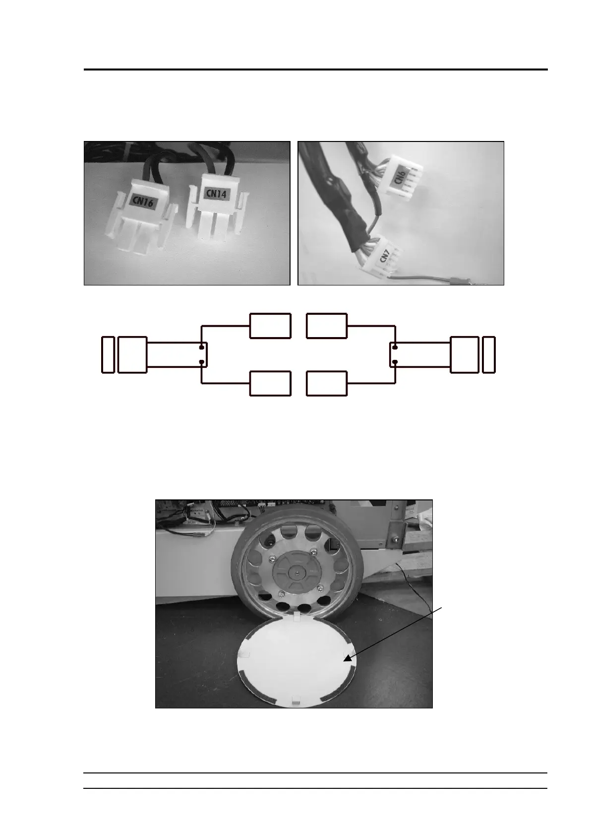
9. As shown in Fig. 6-55, detach the wheel cover.
Fig. 6-55 Remove the Wheel Cover
Wheel cover
Left-side motor Right-side motor
CN6 CN7
CN14 CN16
(2P)
(2P)
(6P)
(6P)
 Loading...