Configuration
Diagnostics
(local)
SOPAS ETSOPAS ET
PC
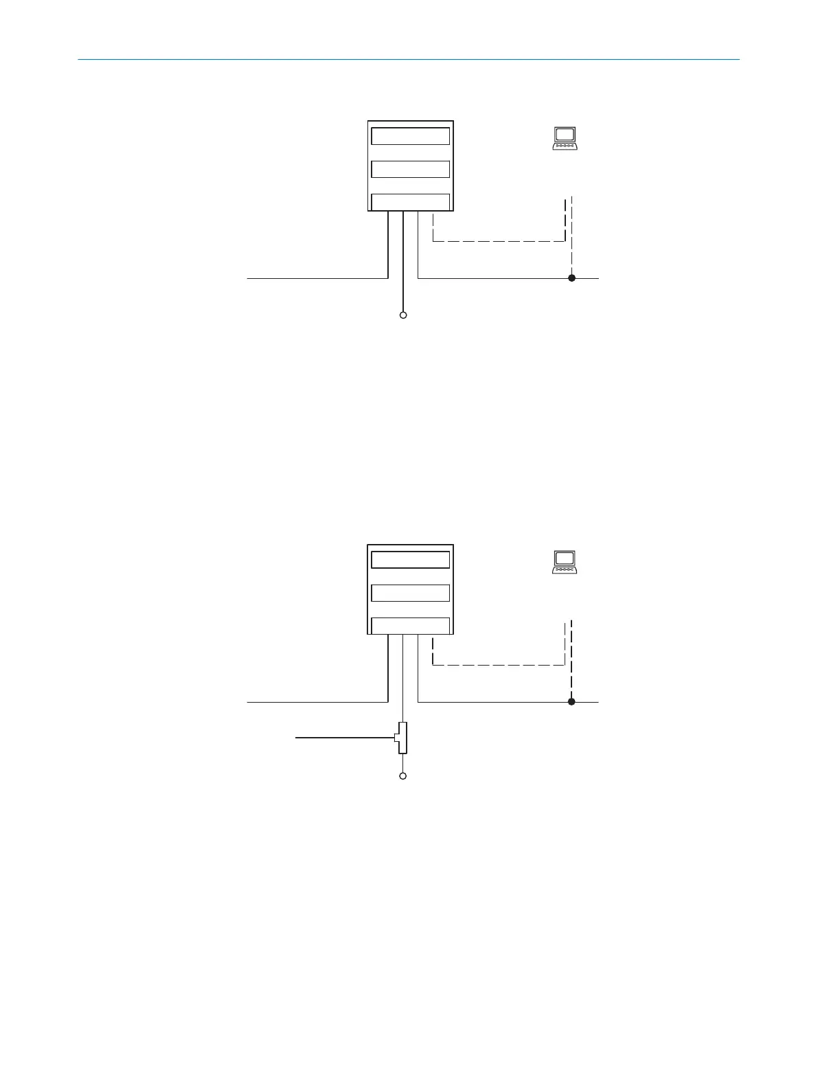
CLV61x Dual Port
(CLV61x-Dx41x)
Aux (USB)
Host /Aux (Ethernet, port 2)Host /Aux (Ethernet, port 1)
V
s
PROFINETPROFINET
Scanner 2
Decoder 3
Interfaces 4
5
1
Figure 6: Block diagram for CLV61x-Dx41x (without switching input)
1
Scanner
2
Decoder
3
Interfaces
4
USB interface
3)
depending on type. Not present on device variants with a memory card
slot.
5
Configuration or diagnostics (local)
6
Supply voltage V
S
= U
V
Configuration
1)
Diagnostics
(local)
SOPAS ETSOPAS ET
PC
CLV61x Dual Port
(CLV61x-Dx52x)
Aux (USB)
Host /Aux (Ethernet, port 2)Host /Aux (Ethernet, port 1)
V
s
PROFINETPROFINET
Read trigger
(switching input) 1
Scanner 2
Decoder 3
Interfaces 4
T distributor
2)
6
1) Alternative: GSD configuration (centrally via the PROFINET controller) 8
2) Male connector, M12, 4-pin, A-coded splitted to 2 x female connector M12, 5-pin, A-coded) 9
5
7
Figure 7: Block diagram for CLV61x-Dx52x (with switching input)
1
Scanner
2
Decoder
3
Interfaces
4
USB interface
3)
depending on type. Not present on device variants with a memory card
slot.
5
Configuration or diagnostics (local)
6
T-connector
7
Supply voltage V
s
3)
Service interface, for temporary use only
PRODUCT DESCRIPTION 3
8017842/ZOK7/2019-02-01 | SICK O P E R A T I N G I N S T R U C T I O N S | CLV61x DualPort (PROFINET)
19
Subject to change without notice
 Loading...


