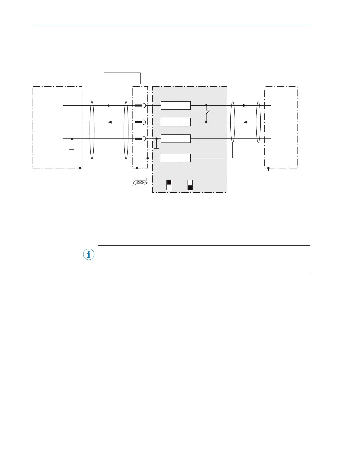
14.5.4 Wiring serial host interface RS-232 of the device in the CDB620-001
Device = CLV61x-xx0xxx (serial variant)
Device
1 CDB620-001 Host
5
.
.
.
TxD
RxD
RxD
TxD
GND
GND
GND
9
7
43
T‒/TxD
44
R‒/RxD
42
GND
6
Shield
RS-232 RS-232
422
485
S6 : RS
ON
OFF
S7: Term 485
S6
422485
110
15
6
11
5
3
Cable 2
Figure 43: Wiring data interface RS-232 of the device in the connection module CDB620-001
1
Device
2
Connecting cable permanently connected with the device (male connector, D-Sub-HD, 15-pin)
3
Connection module: female connector, D-Sub-HD, 15-pin
NOTE
Activate the RS-232 data interface in the device with a configuration tool, e.g., the
configuration software SOPAS ET.
14.5.5 Wiring the CAN interface in the CDB620-001
Device = CLV61x-xx0xx (serial variant)
ANNEX 14
8017840/19OF/2021-10-28 | SICK O P E R A T I N G I N S T R U C T I O N S | CLV61x
79
Subject to change without notice
 Loading...


