1
Trigger sensor, e.g. for read cycle generation
2
External supply voltage V
S ext
3
Input voltage V
in
4
PNP sensor
5
Supply voltage V
S
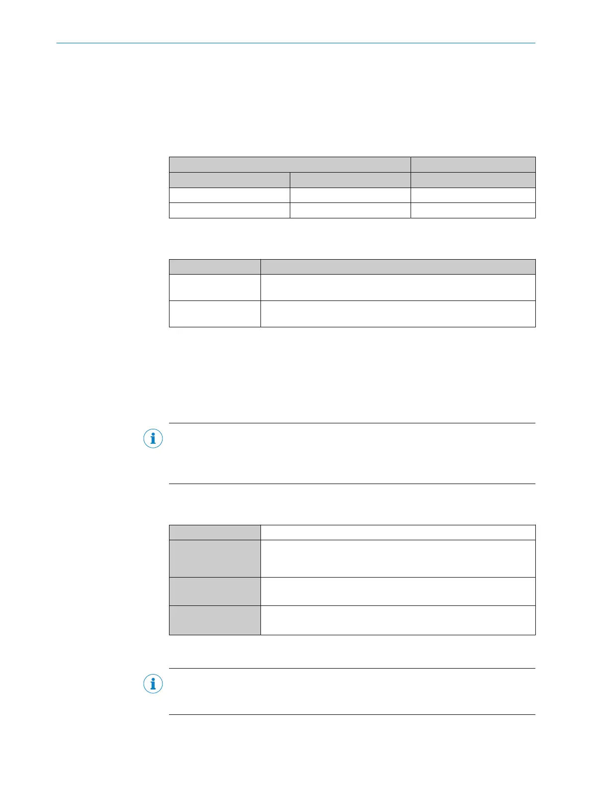
Table 38: Assignment of placeholders to the digital inputs
CDM420-0001 Device
Terminal A Signal B External input C
18 Aux In 1 1
19 Aux In 2 2
Function of switch S6
Table 39: Switch S6: SGND - GND
Switch setting Function
ON GND of the trigger sensor connected with GND of CDM420-0001 and
CMC600
OFF Trigger sensor connected volt-free at CDM420-0001 and CMC600
Common, isolated reference potential of all digital inputs is SGND.
Functional principle of the external digital inputs
The optional CMC600 parameter cloning module in combination with the CDB or CDM
connection module offers two additional physical digital inputs for the device. The
inputs are available at the respective terminals of the connection module. To distin‐
guish them from the physical digital inputs directly on the device, these addition inputs
via the CMC600 are designated as “external inputs”.
NOTE
The CMC600 transmits the switching signals of the external digital inputs as statuses to
the local inputs of the device via its serial data interface.
The digital inputs are not suitable for time-critical applications.
Characteristic data of the digital inputs
Table 40: Characteristic data of the digital inputs “External input 1” and “External input 2”
Type Switching
Switching behavior Power to the input starts the assigned function, e.g. start read cycle.
Default setting in the device: logic not inverted (active high), debounce
time 10 ms
Properties
•
Opto-decoupled, reverse polarity protected
•
Can be wired with PNP output of a trigger sensor
Electrical values Low: V
in
1)
≤ 2 V; I
in
2)
≤ 0.3 mA
High: 6 V ≤ V
in
≤ 30 V; 0.7 mA ≤ I
in
≤ 5 mA
1)
Input Voltage
2)
Input current
NOTE
Assign the functions for the digital inputs in the device using a configuration tool, e.g.,
the configuration software SOPAS ET.
14 ANNEX
96
O P E R A T I N G I N S T R U C T I O N S | CLV61x 8017840/19OF/2021-10-28 | SICK
Subject to change without notice
 Loading...


