Chapter 6 Operating Instructions
CLV62x Bar Code Scanner
52 © SICK AG · Division Auto Ident · Germany · All rights reserved 8011965/S345/2008-04-16
Electrical installation
The "Sensor 2" switching input has the following functions, among others:
Trigger source for
• Incremental encoder input
• Reading pulse generator for reading pulse end
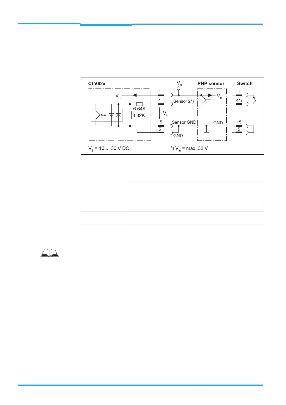
Fig. 6-7: Wiring the "Sensor 2" switching input on the 15-pole D-Sub-HD plug
Important The ratings for "Sensor 1" and "Sensor 2" are identical.
Tab. 6-7: Ratings for the switching inputs
¾ Connect switching inputs depending on application.
Switching behaviour Power fed to the input opens the internal reading gate of the bar code
scanner.
(Default setting: active high; debouncing: max. 30 ms (standard))
Features – Optodecoupled, reverse polarity protected
– Can be wired with the PNP output of a sensor
Electrical values Low: |V
in
| ≤ 2 V; |I
in
| ≤ 0.3mA
High: 6 V ≤ |V
in
| ≤ 32 V; 0.7 mA ≤ |I
in
| ≤ 5.0 mA
Important
To wire the switching inputs using connection module CDB620 or CDM420, see operating
instructions "Connection Module CDB620" (no. 8012119, German/English) or "Connection
Module CDM420-0001" (no. 8010004, German/English).