6
Ground potential difference
7
Grounding point 1
8
Metal housing
9
Shielded electrical cable
If these conditions are not fulfilled, equipotential bonding currents can flow along the
cable shielding between the devices due to differing ground potentials and cause the
hazards specified. This is, for example, possible in cases where there are devices within
a widely distributed system covering several buildings.
Remedial measures
The most common solution to prevent equipotential bonding currents on cable shields
is to ensure low-impedance and current-carrying equipotential bonding. If this equipo‐
tential bonding is not possible, the following solution approaches serve as a suggestion.
NOTICE
We expressly advise against opening up the cable shields. This would mean that the
EMC limit values can no longer be complied with and that the safe operation of the
device data interfaces can no longer be guaranteed.
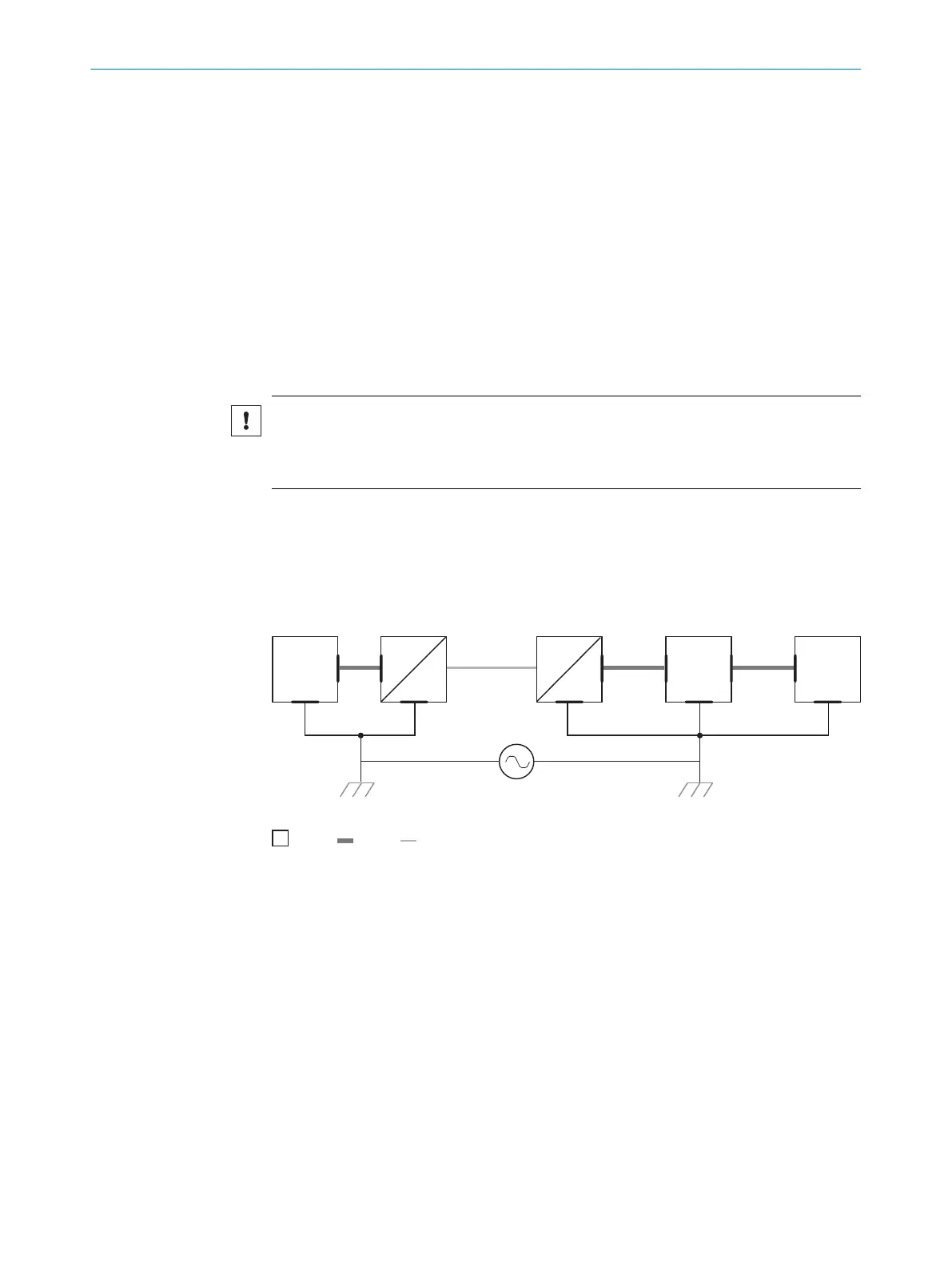
Measures for widely distributed system installations
On widely distributed system installations with correspondingly large potential differen‐
ces, the setting up of local islands and connecting them using commercially available
electro-optical signal isolators is recommended. This measure achieves a high degree
of resistance to electromagnetic interference.
Electro-
optical
signal
isolator
Electro-
optical
signal
isolator
Power
Supply
SICK
Device
1 2 2 43
6 5
System
Controller
= 7
= 8
= 9
Figure 5: Example: Prevention of equipotential bonding currents in the system configuration by
the use of electro-optical signal isolators
1
System controller
2
Electro-optical signal isolator
3
Device
4
Voltage supply
5
Grounding point 2
6
Grounding point 1
7
Metal housing
8
Shielded electrical cable
9
Optical fiber
The use of electro-optical signal isolators between the islands isolates the ground loop.
Within the islands, a stable equipotential bonding prevents equalizing currents on the
cable shields.
6
ELECTRICAL INSTALLATION
24
O P E R A T I N G I N S T R U C T I O N S | Lector85x 8027859/1INN/2023-03-08 | SICK
Subject to change without notice