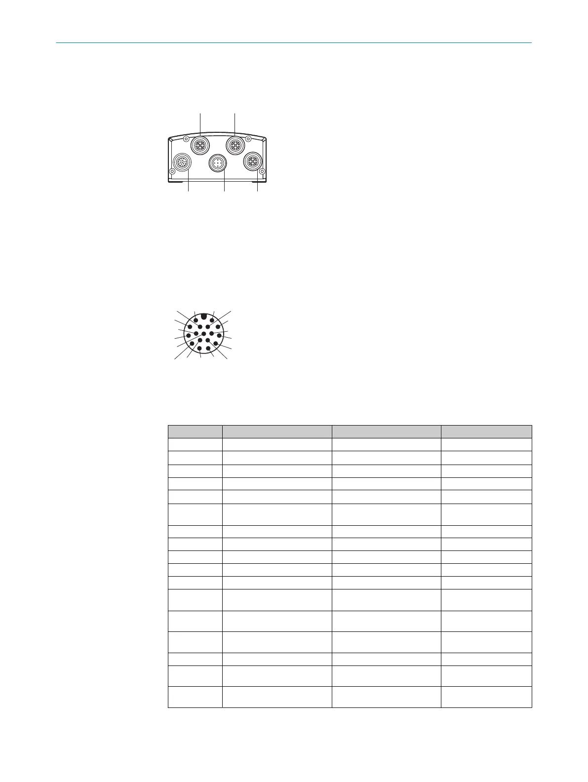
6.3 Connections and pin assignment
Overview
1
P1: GB Ethernet 1
2
P2: GB Ethernet 2
3
P3: GB Ethernet 3
4
X2: Power/CAN
5
X1: Power/CAN/serial interface/IO
Power/CAN/serial interface/IO
1
2
6 714
12
3
4
5
8
9
10
11
13
15
17
16
Figure 7: Male connector, M12, 17-pin, A-coded
The serial interface and the digital inputs and outputs are not available. Do not connect
the associated pins.
PIN Signal Description Information
1 GND Supply voltage: 0 V
2 V
S
Supply voltage: DC 24V ±20%
3 CAN L CAN-Bus LOW (IN/OUT)
4 CAN H CAN-Bus HIGH (IN/OUT)
5 TD+ (RS-422), Host Host interface (sender+) Not available.
6 TD- (RS-422), Host
TxD (RS-232), host
Host interface (sender-) Not available.
7 TxD (RS-232), Aux AUX interface (sender) Not available.
8 RxD (RS-232), Aux AUX interface (receiver) Not available.
9 SensGND Ground digital inputs 1 and 2 Not available.
10 Sensor 1 Digital input 1 (insulated) Not available.
11 RD+ (RS-422) Host Host interface (receiver+) Not available.
12 RD- (RS-422), host
RxD (RS-232), host
Host interface (receiver–) Not available.
13 DIO 3 Configurable digital input and out‐
put 3
Not available.
14 DIO 4 Configurable digital input and out‐
put 4
Not available.
15 Sensor 2 Digital input 2 (insulated) Not available.
16 DIO 5 Configurable digital input and out‐
put 5
Not available.
17 DIO 6 Configurable digital input and out‐
put 6
Not available.
6 ELECTRICAL INSTALLATION
26
O P E R A T I N G I N S T R U C T I O N S | Lector85x 8027859/1INN/2023-03-08 | SICK
Subject to change without notice