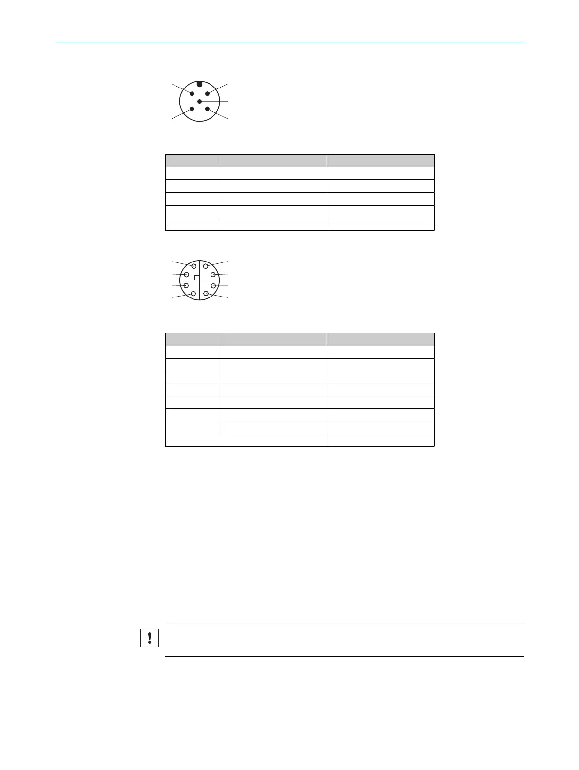
Power/CAN
Figure 8: Male connector, M12, 5-pin, A-coded
PIN Signal Description
1 – Shielding
2 V
S
Supply voltage: DC 24V ±20%
3 GND Supply voltage: 0 V
4 CAN H CAN-Bus HIGH (IN/OUT)
5 CAN L CAN-Bus LOW (IN/OUT)
GB Ethernet
Figure 9: Female connector, M12, 8-pin, X-coded
PIN Signal Description
1 TRD0_P Sender+/receiver+ 0
2 TRD0_N Sender–/receiver– 0
3 TRD1_P Sender+/receiver+ 1
4 TRD1_N Sender–/receiver– 1
5 TRD3_P Sender+/receiver+ 3
6 TRD3_N Sender–/receiver– 3
7 TRD2_N Sender–/receiver– 2
8 TRD2_P Sender+/receiver+ 2
Further topics
•
Information on interfaces: Technical data
6.4 Network services and ports
Available network services and ports can be viewed in SOPASair under Diagnostics >
Cybersecurity.
6.5 Connecting
6.5.1 Connecting the product electrically
Important information
NOTICE
Observe the wiring instructions, see "Wiring instructions", page 22.
Approach
1. Ensure the voltage supply is not connected.
2. Connect the product according to the connection diagram.
ELECTRICAL INSTALLATION 6
8027859/1INN/2023-03-08 | SICK O P E R A T I N G I N S T R U C T I O N S | Lector85x
27
Subject to change without notice