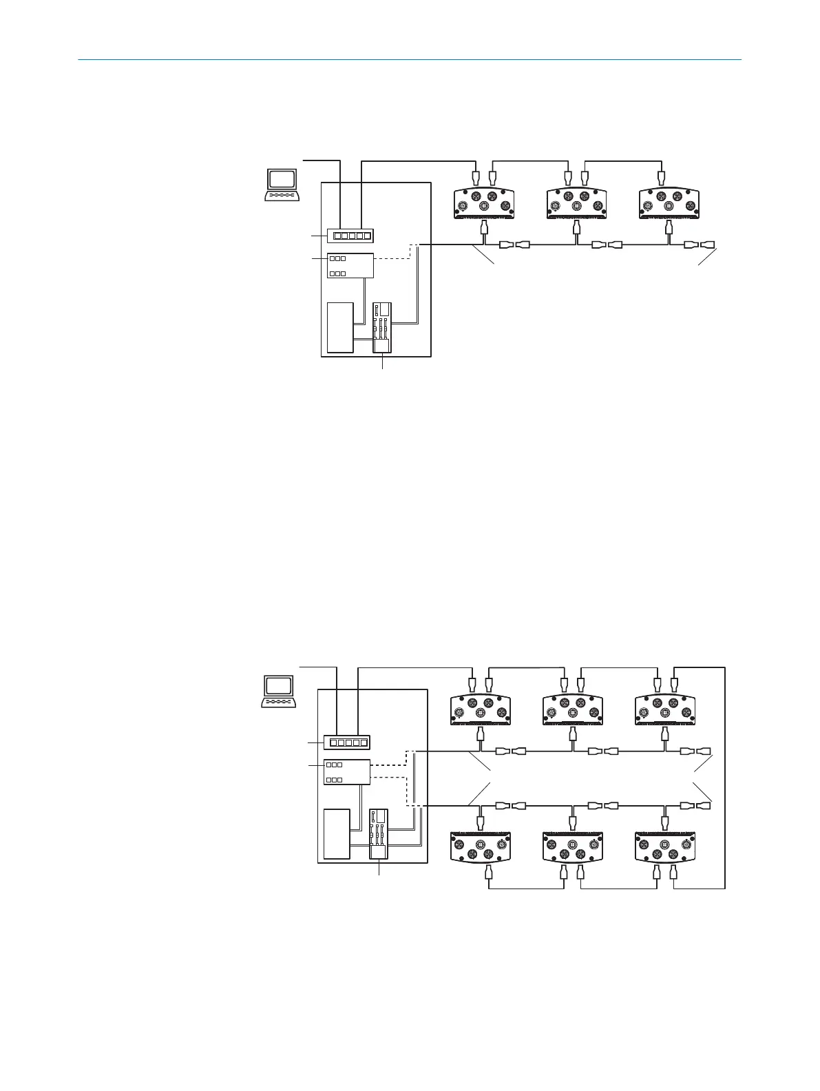
6.5.4 CAN connection principle
Connection to 3 devices
X1 X2 P3
P1 P2 P1 P2
P1 P2
X1 X2 P3 X1 X2 P3
...
...
SOPASSOPAS
1
2
8
7
3
4
6
5
Switch
T4A
Ethernet Gbit
9
CAN
Track and
Trace Controller
Track and
Trace Controller
Fuse BlockFuse Block
ß
CAN
Figure 10: Connection principle for CAN with track and trace controller, 3 devices
1
Software for Integration Package Analytics, image output
2
Control cabinet
3
Switch
4
Track and trace controller (e.g., MSC800, SIM2000)
5
Fuse box
6
26V supply voltage
7
CAN connection A
8
Gbit P1 and P2 Ethernet: image output, parameterization
9
CAN: power, increment, trigger, focus, code
ß
CAN male connector with terminating resistor
Connection to 6 devices
X1 X2 P3
P1 P2
P1 P2P1 P2
P1 P2
P1 P2
P1 P2
X1 X2 P3 X1 X2 P3
X1 X2 P3 X1 X2 P3 X1 X2 P3
...
...
SOPASSOPAS
1
2
9
7
8
3
4
6
5
Switch
T4A
Ethernet Gbit
ß
CAN
Fuse BlockFuse Block
à
CAN
Track and
Trace Controller
Track and
Trace Controller
Figure 11: Connection principle for CAN with track and trace controller, 6 products
1
Software for Integration Package Analytics, image output
2
Control cabinet
3
Switch
4
Track and trace controller (e.g., MSC800, SIM2000)
5
Fuse box
ELECTRICAL INSTALLATION 6
8027859/1INN/2023-03-08 | SICK O P E R A T I N G I N S T R U C T I O N S | Lector85x
29
Subject to change without notice