Connections
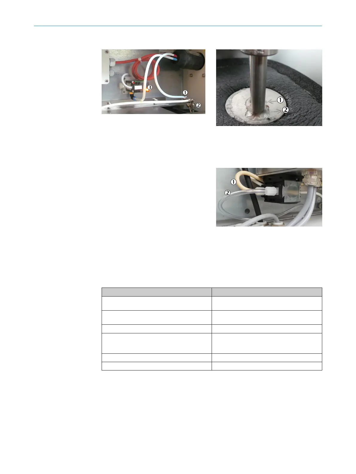
1
Cooler inlet (observe designation on
cooler)
2
Cooler outlet (observe designation on
cooler)
3
Solenoid valve KK10, always acti‐
vated during normal operation (LED
on)
1
Gas inlet
2
Gas outlet
1
Condensate inlet in hose pump
2
Condensate outlet from hose pump
b
Lay all PTFE tubes into the enclosure from the bottom.
b
Enclosure duct of heated sample gas line: see "Installing the sample gas line",
page 22.
b
Connect the lines.
Line Connect to:
Line marked red (sample gas line) from heated sam‐
ple gas line
Cooler: Gas inlet (see Figure above)
Line marked blue (instrument air/span gas) from
heated sample gas line
Solenoid valve KK10: Outlet “A”
PTFE line from external instrument air Solenoid valve KK10: Inlet “R”
PTFE line from external span gas (only possible for
measuring point 1)
Solenoid valve KK10: Inlet “P”
If span gas is not connected: Close off the inlet with
a dummy plug.
PTFE line sample gas outlet to distribution unit Cooler: Gas outlet (see Figure above)
Condensate outlet Cooler: Condensate outlet of hose pump
Cooler
The sample gas cooler is system-specific.
b
For further information concerning the sample gas cooler, see the Operating
Instructions of the sample gas cooler.
Condensate outlet
The condensate outlet is at the bottom of the cooler.
Acid condensate escapes from the condensate outlet.
2 INSTALLATION
26
T E C H N I C A L I N F O R M A T I O N | MARSIC200 8017324/15A2/V6-0/2019-10 | SICK
Subject to change without notice
 Loading...


