Alarme = saída de alarme (ver tabela 32 e Funções adicionais)
n. c. = não conectado
NC = abridor
NO = fechador
Q / Q = saídas de comutação
ET/Teste = Entrada de teste (ver tabela 32 e tabela 37)
45.1
WT24-2Bxxx, WT24-2Vxxx
U
B
: 10 ... 30 V CC, ver "Dados técnicos", página 60
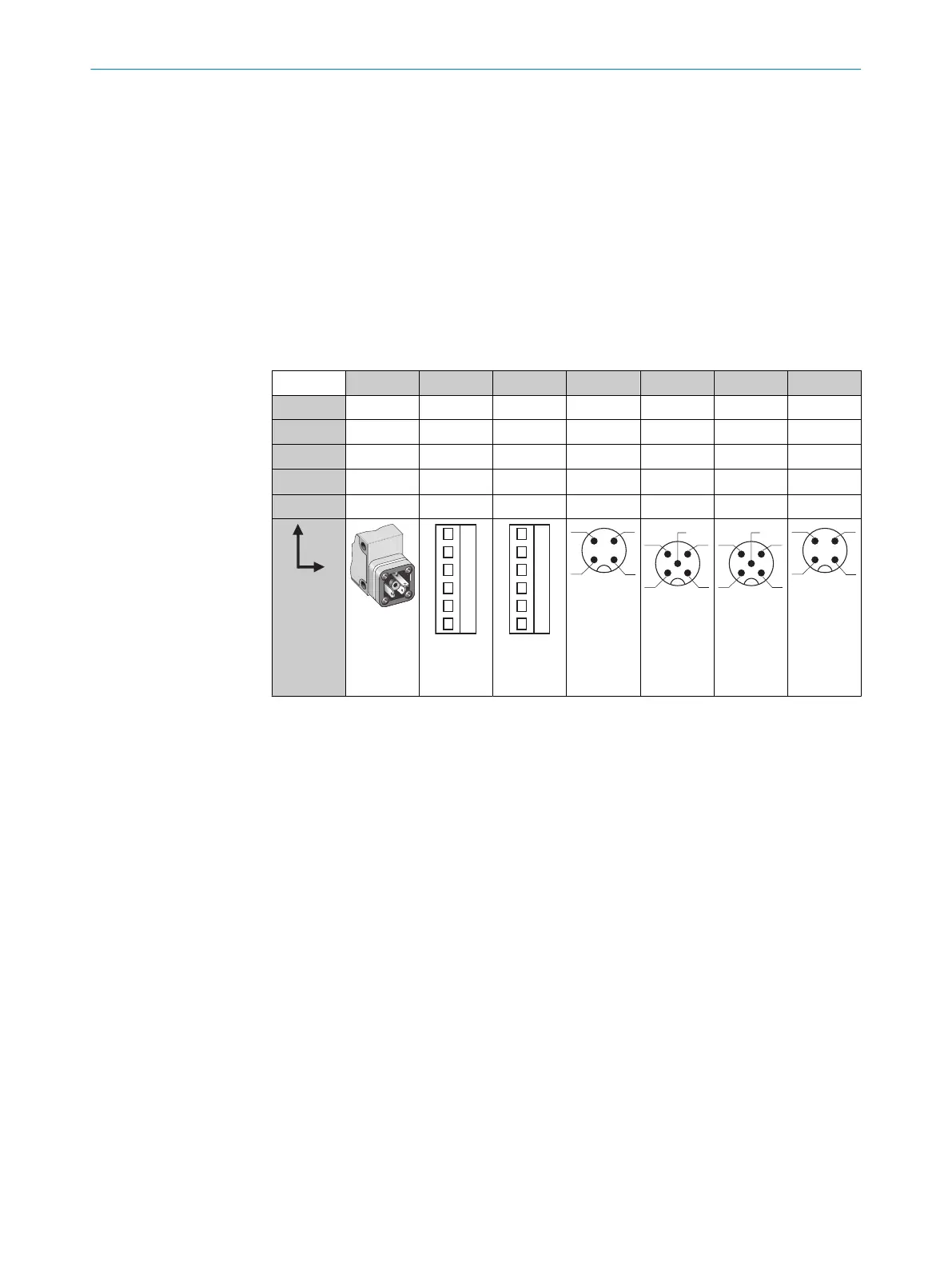
Tabela 32: CC
WT24-2 B3x3 B2x0 V2x0 B4x0 V5x0 V510S15 B410S25
1 + (L+) + (L+) + (L+) + (L+) + (L+) + (L+) + (L+)
2 - (M) - (M) - (M) Teste Teste Alarme n. c.
3
Q/Q
- Alarme - (M) - (M) - (M) - (M)
4 -
Q/Q Q/Q Q/Q Q/Q Q/Q Q/Q
5 - Teste Teste - Alarme Teste -
I
N
= 4 A
0,14 ...
1,5 mm
2
I
N
= 4 A
0,14 ...
1,5 mm
2
I
N
= 4 A
45 INSTALAÇÃO ELÉTRICA
52
8008784.14BT | SICK
Subject to change without notice