Explicaciones relativas al esquema de conexión (tablas 2-7), que están subdivididas en
dispositivos CC y CA/CC:
Alarma = salida de alarma (véase tabla 52 y Funciones adicionales)
n. c. = no conectado
NC = contacto normalmente cerrado
NO = contacto normalmente abierto
Q / Q = Salidas conmutadas
TE/Test = entrada de prueba (véase tabla 52 y tabla 57)
71.1
WT24-2Bxxx, WT24-2Vxxx
U
B
: 10 . 30 V CC, véase "Datos técnicos", página 91
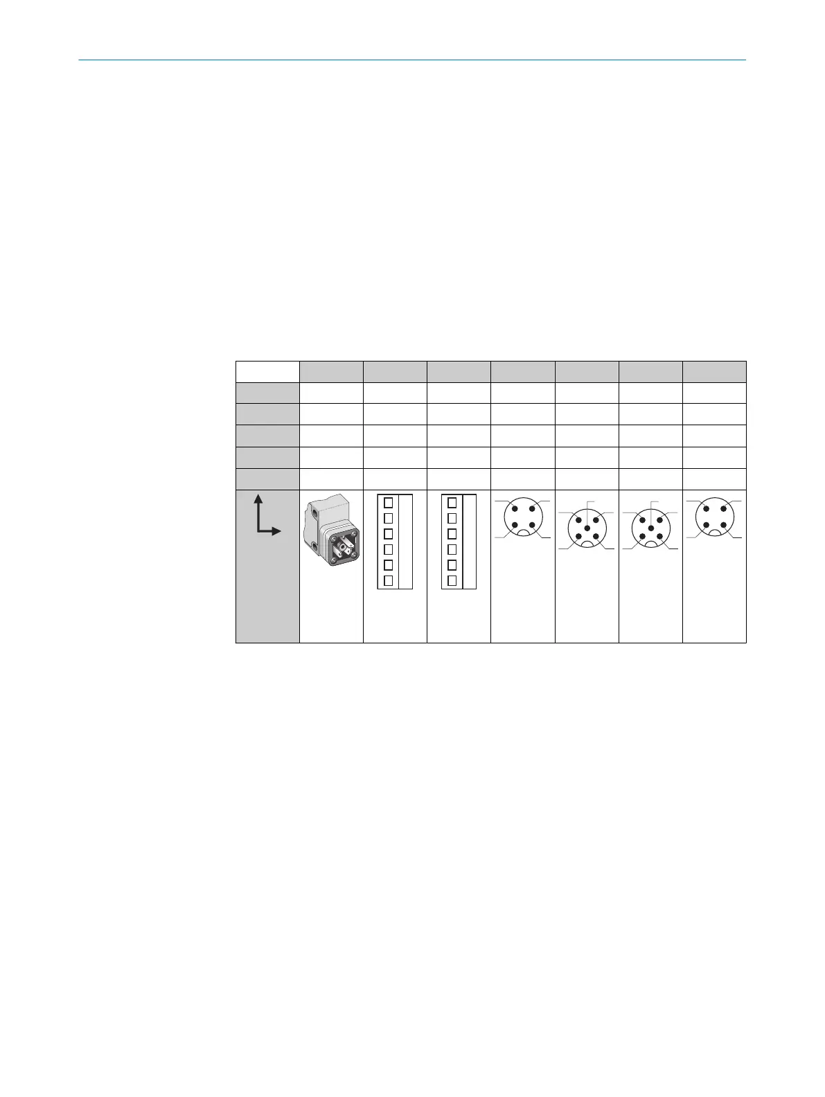
Tabla 52: CC
WT24-2 B3x3 B2x0 V2x0 B4x0 V5x0 V510S15 B410S25
1 + (L+) + (L+) + (L+) + (L+) + (L+) + (L+) + (L+)
2 - (M) - (M) - (M) Test Test Alarma n. c.
3
Q/Q
- Alarma - (M) - (M) - (M) - (M)
4 -
Q/Q Q/Q Q/Q Q/Q Q/Q Q/Q
5 - Test Test - Alarma Test -
I
N
= 4 A
0,14 ...
1,5 mm
2
I
N
= 4 A
0,14 ...
1,5 mm
2
I
N
= 4 A
INSTALACIÓN ELÉCTRICA 71
8008784.14BT | SICK
Subject to change without notice
83