NC = normally closed
NO = normally open
Q / Q = switching outputs
TE/Test = test input (see table 2 and table 7)
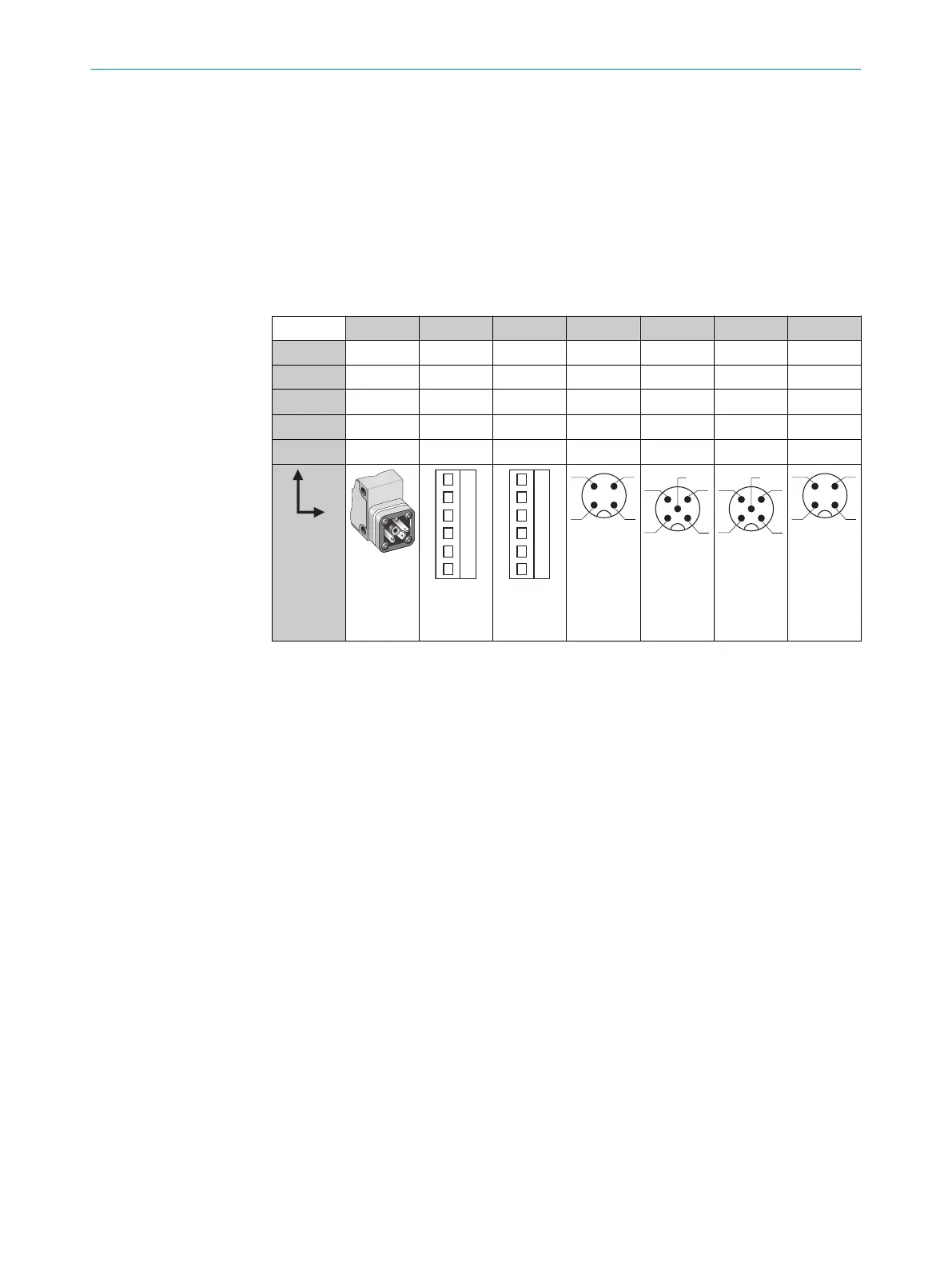
6.1 WT24-2Bxxx, WT24-2Vxxx
U
B
: 10 . 30 V DC, see "Technical data", page 14
Table 2: DC
WT24-2 B3x3 B2x0 V2x0 B4x0 V5x0 V510S15 B410S25
1 + (L+) + (L+) + (L+) + (L+) + (L+) + (L+) + (L+)
2 - (M) - (M) - (M) Test Test Alarm n. c.
3
Q/Q
- Alarm - (M) - (M) - (M) - (M)
4 -
Q/Q Q/Q Q/Q Q/Q Q/Q Q/Q
5 - Test Test - Alarm Test -
I
N
= 4 A
0.14 ...
1.5 mm
2
I
N
= 4 A
0.14 ...
1.5 mm
2
I
N
= 4 A
ELECTRICAL INSTALLATION 6
8008784.14BT | SICK
Subject to change without notice
7
 Loading...


