Tabella 45: AC/DC relè
relè
3
WT24-2R2x0
H
I
max.
= 4A @ 250V AC
4A @ 24V DC
0.125A @ 250 V DC
UL: 4A @ 250 V AC, general
use
4A @ 250 V AC, resistive
(NO)
3A @ 250 V AC, resistive
(NC)
4A @ 24 V DC, NO, general
use
3A @ 24 V DC, NC, general
use
R300
B300 (NO contacts only)
D
WT24-2R5x8, WT24-2R5x9: I
max.
= 2.5A @ 250 V AC, 2.5A @ 24 V DC, 0.125A @ 250 V
DC
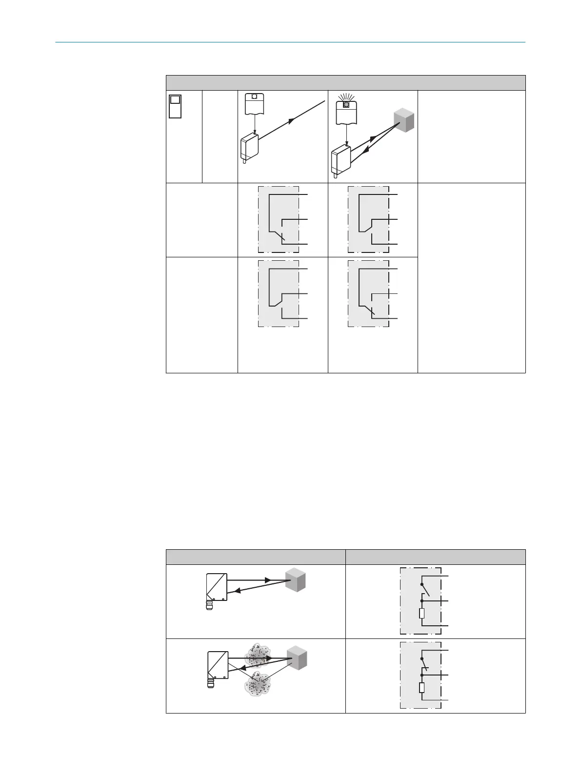
59 Funzioni supplementari
Alarm
Uscita allarme: il sensore (WT24-2Vxxx) dispone di un’uscita di comunicazione di previ‐
sta avaria (“allarme” nello schema di collegamento [v. "WT24-2Bxxx, WT24-2Vxxx",
pagina 67]), che indica quando il sensore è ancora pronto per il funzionamento, ma
solo in modo limitato. In questo caso l’indicatore LED lampeggia. Possibili cause: sen‐
sore sporco, sensore disallineato. In buono stato: LOW (0), in caso di molto sporco HIGH
(1).
Tabella 46: Allarme
Allarme (≤ 100 mA)
FUNZIONI SUPPLEMENTARI 59
8008784.14BT | SICK
Subject to change without notice
69

 Loading...


