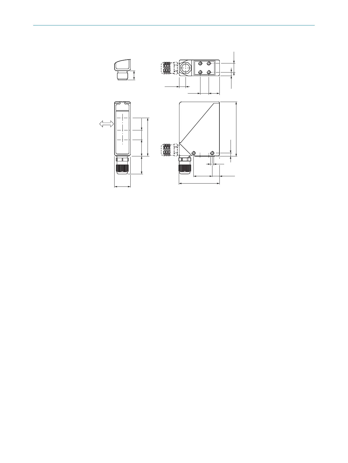
13.1 Dimensional drawing
15
(0.59)
26
(1.02)
61 (2.40)
max. 32
(1.26)
27
(1.06)
10
(0.39)
M5
87.5 (3.44)
4.7
(0.19)
11.8
(0.46)
30 (1.18)
65 (2.56)
1
2
8
9
14
(0.55)
6.5
(0.26)
14
(0.55)
17.5
(0.69)
7
3
4
5
6
14,4
(0.57)
9
Figure 8: Dimensional drawing
1
Alignment sight
2
LED signal strength indicator
3
Standard direction of the material being detected
4
Center of optical axis, sender
5
Center of optical axis, receiver (close range)
6
Center of optical axis, receiver (far range)
7
M5 threaded mounting hole, 6 mm deep
8
M5 threaded mounting hole, through-hole
9
M16 screw fixing and plug rotatable by 90°
13 TECHNICAL DATA
16
8008784.14BT | SICK
Subject to change without notice
 Loading...


