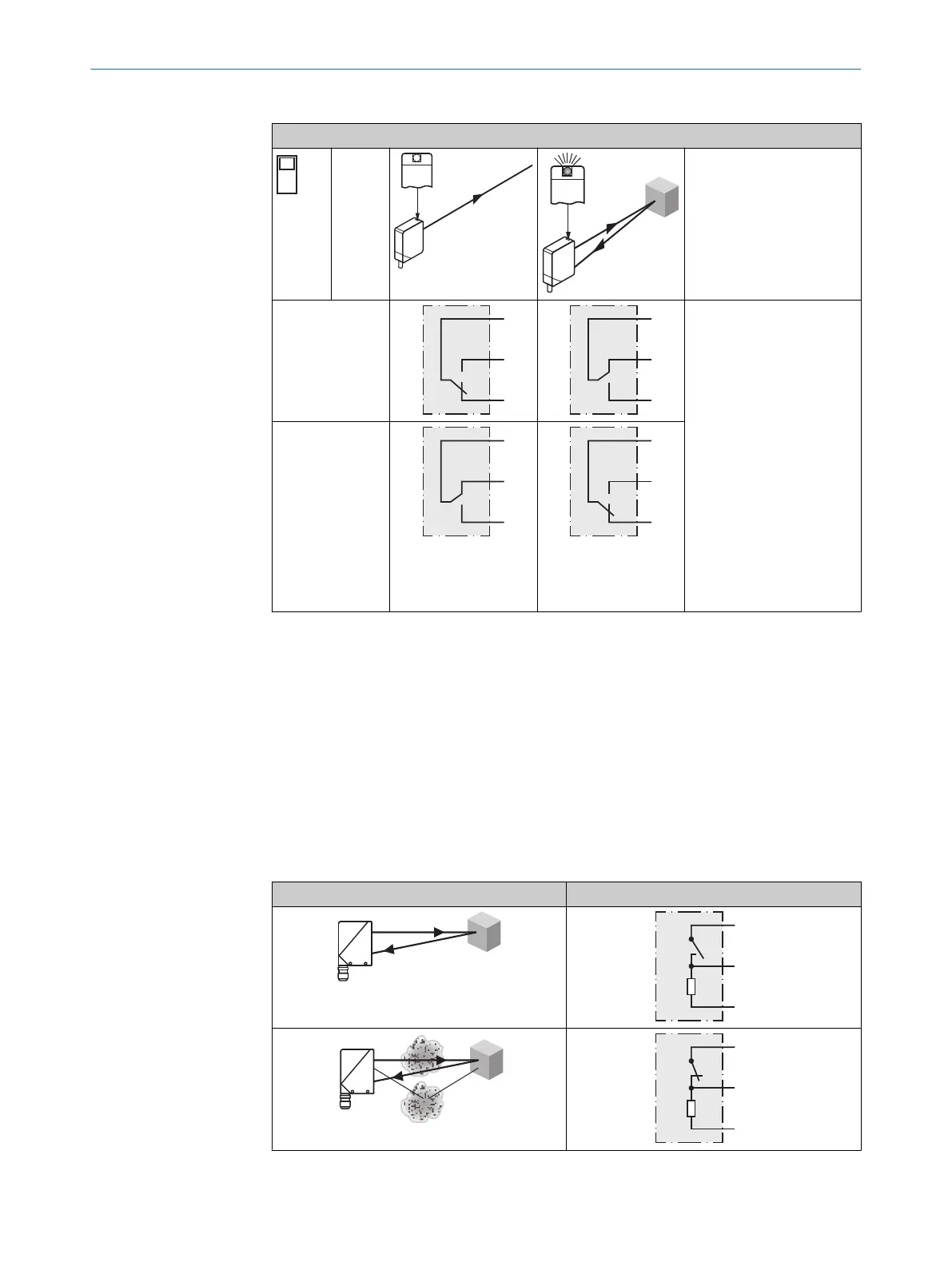
Tabla 55: Relé CA/CC
Reles
3
WT24-2R2x0
H
I
max.
= 4A @ 250V CC
4A @ 24 V CC
0.125A @ 250 V CC
UL: 4A @ 250 V AC, general
use
4A @ 250 V AC, resistive
(NO)
3A @ 250 V AC, resistive
(NC)
4A @ 24 V DC, NO, general
use
3A @ 24 V DC, NC, general
use
R300
B300 (NO contacts only)
D
WT24-2R5x8, WT24-2R5x9: I
max.
= 2.5A @ 250 V AC, 2.5A @ 24 V DC, 0.125A @ 250 V
DC
72 Funciones adicionales
Alarma
Salida de alarma: el sensor (WT24-2Vxxx) dispone de una salida para preavisos de fallo
(“Alarm” en el diagrama de conexiones [véase "WT24-2Bxxx, WT24-2Vxxx", página 83])
que indica cuándo el sensor puede usarse pero con limitaciones. En este caso el LED
indicador parpadeará. Causas posibles: el sensor está sucio o desajustado. Si está en
buen estado: LOW (0), si está muy sucio: HIGH (1).
Tabla 56: Alarm
Alarm (≤ 100 mA)
FUNCIONES ADICIONALES 72
8008784.14BT | SICK
Subject to change without notice
85