Drive Amplifier SD4B
Interface Property Value
Max. output current 50 mA
Accuracy ±0,5 %
X15 10 V reference voltage
(VREF 10V)
Short-circuit proof Yes
Low level (0 V = logic 0 = L) < 2.6 V
High level (24 V = logic 1 = H) > 12.5 V
Sampling rate software 4 kHz
Electric strength 35 V
Typical delay time L → H < 8 µs
Typical delay time H → L < 19 µs
X15 digital inputs IN1 to IN5
▶ referenced to GND
Typical current consumption 1.2 mA
Low level (0 V = logic 0 = L) < 0.98 V
High level (24 V = logic 1 = H) > 6.5 V
Sampling rate FPGA 2 MHz
Electric strength 35 V
Typical delay time L → H < 3.5 µs
Typical delay time H → L < 1 µs
X15 digital inputs IN4, IN5
▶ referenced to GND
▶ used as touch probe input
Typical current consumption 1.2 mA
Sampling rate software 4 kHz
Short-circuit proof Yes
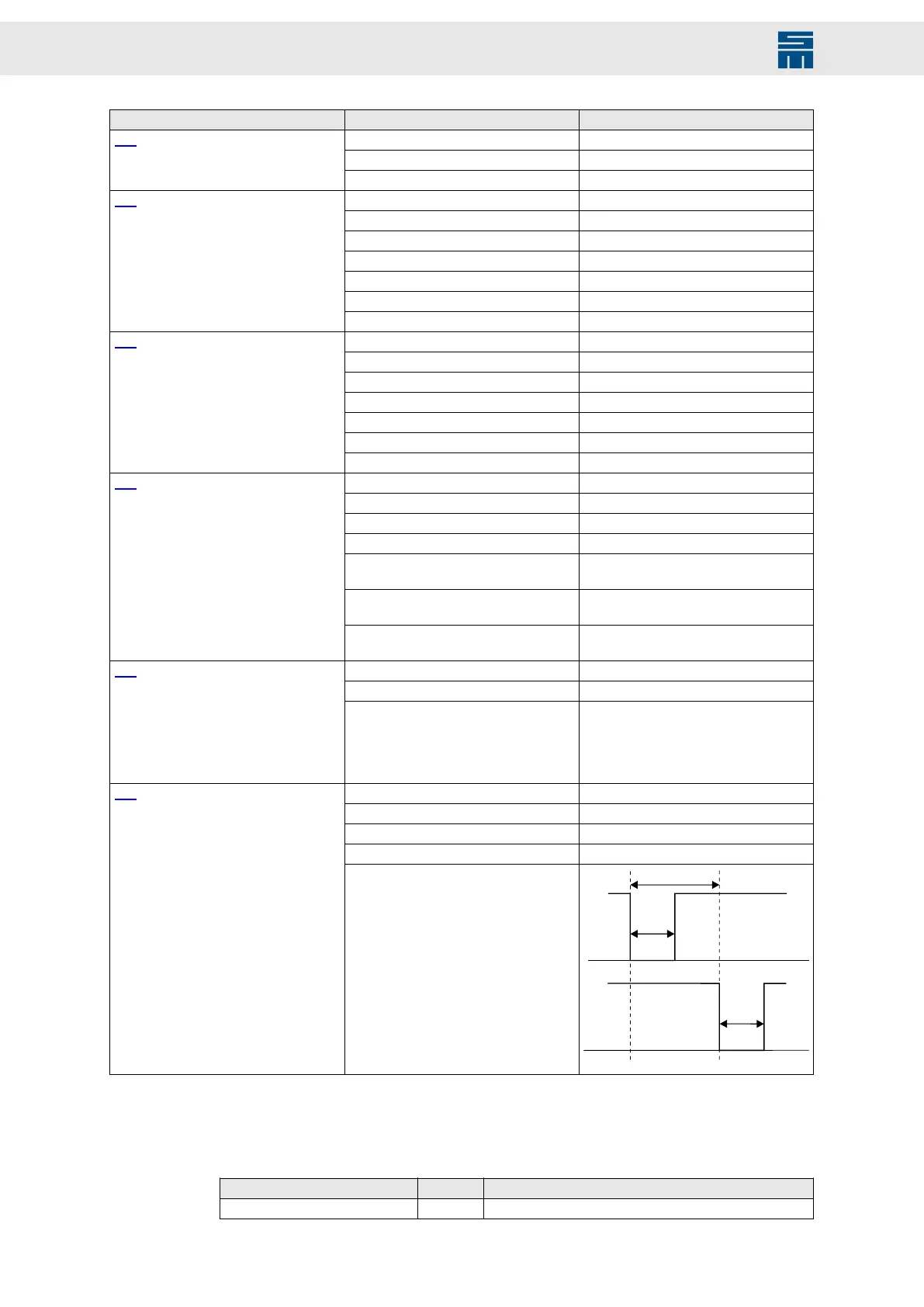
Max. operate time < 13 µs
Max. release time < 6 µs
Max. load capacity individually 20 mA
(100 mA with 24 V logic supply)
Max. load capacity together 100 mA
(400 mA with 24 V logic supply)
X15 digital outputs OUT1 to OUT5
▶ referenced to GND
▶ high-side or low-side configurable via
parameters (only as group); high-side
≜ 24 V at X15/A2
Others For ohmic load only,
no internal free-wheeling path
Sensor range 0.3 kΩ to 2.5 kΩ
Galvanic isolation No
X15 motor protection (M-TEMP)
Supported sensor types PTC
NTC
PT1000
KTY84130
KTY83122
Voltage range: safe input level low < 2.4 V
Voltage range: safe input level high >18 V
Electric strength 48 V
Response time 4 ms
X15 safety circuit
▶ STO inputs
OSSD test signals
Tab. 4: Technical data of the interfaces
Tab. 4: Technical data of the interfaces
5.4.7 Motor Control
Sampling rate Unit Value
Sampling rate commutation kHz 2 × switching frequency
Tab. 5: Motor control
22 Drive Amplifier SD4B - Hardware Description