7.8.4 Connecting the Motor Protection
INPUT/OUTPUT: The thermal motor protection is evaluated via these connectors.
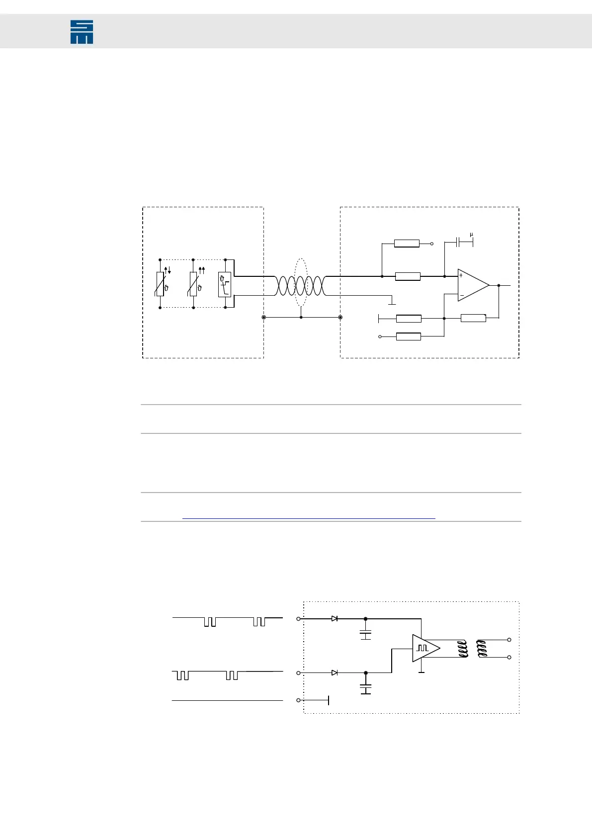
The drive amplifier supports evaluating the temperature monitoring integrated in the mo-
tor. The NTC/PTC behavior of the monitoring is defined in the software (motor parame-
ters). The controller is deactivated as soon as the critical motor temperature is reached.
The following sensor types are available: NTC, PTC, KTY84130, KTY83122 and
PT1000.
Fig. 25: Temperature sensor of the motor
0.1 F
DriveMotor
NTC PTC
KTY 84/130
Thermo
contact
6K8
47K
3K3
3K3
10M
X15 / B6
X15 / B1, B2, B7
Fig. 25: Temperature sensor of the motor
The temperature sensor must have an internal resistor between 250 Ω and 2 kΩ.
Note
If no motor temperature sensor is connected, the input must be connected with GND.
7.8.5 Connecting the Safety Circuit
Note
See also chapter 8.1 “Safety Circuit / Restart Lock (STO)”, page 49.
7.8.5.1 Wiring with OSSD
OSSD = Output Signal Switching Device
Fig. 26: Safety circuit (STO) - wiring with OSSD
Fig. 26: Safety circuit (STO) - wiring with OSSD
45Drive Amplifier SD4B - Hardware Description
Connectors