Connectors
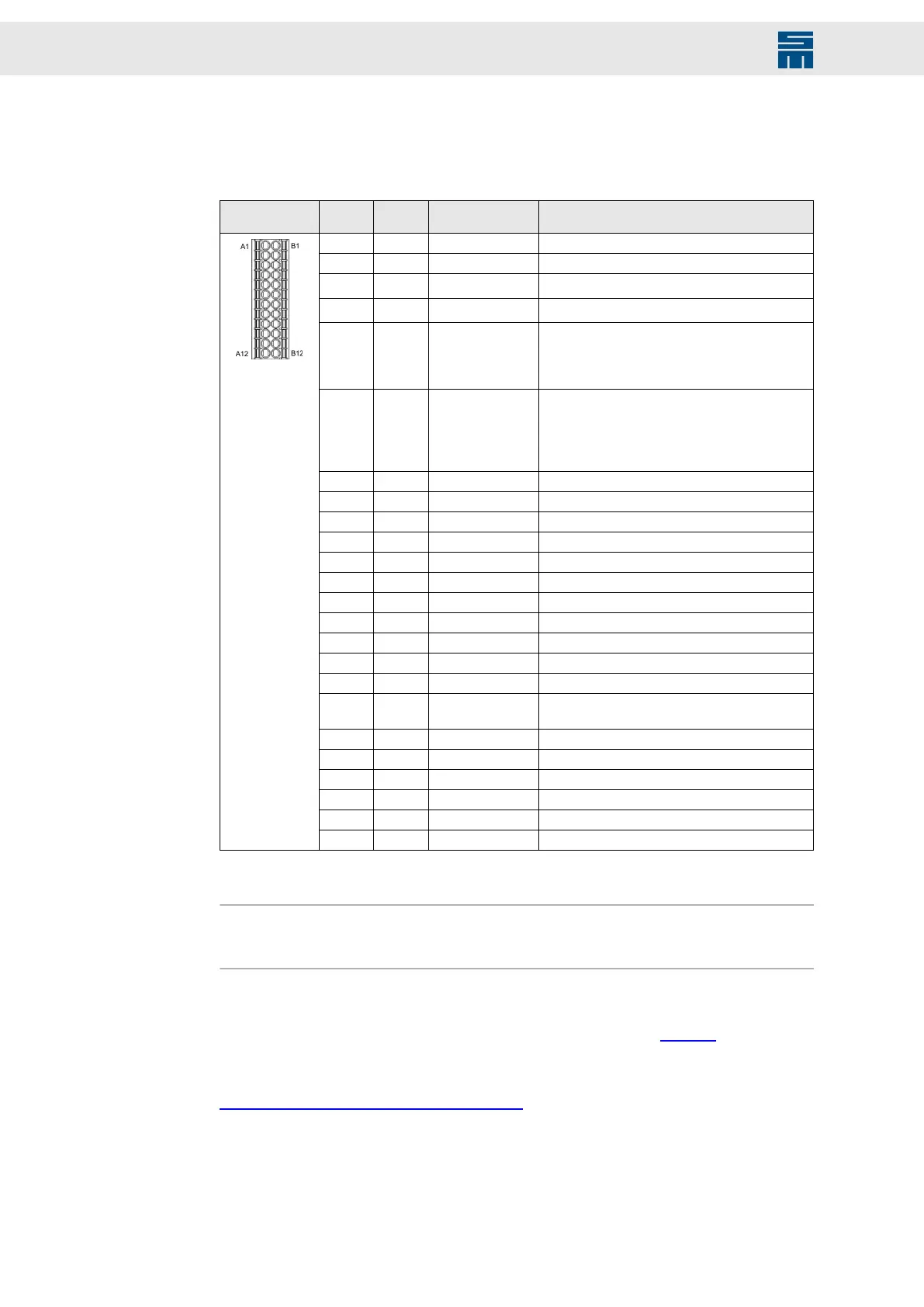
7.8 X15 – Inputs/Outputs / Safety Circuit (STO)
2 ×12-pole Mini-Combicon connector, suitable for mating connector DFMC 1.5/12-
ST-3.5 (Phoenix)
Mating con-
nector X15
Pin I/O Name Meaning
A1 I/O GND Ground
A2 I 24V IN Logic supply 24 V
A3 O
24V OUT
(1)
Logic supply 24 V
A4 O
24V OUT
(1)
Logic supply 24 V
A5 I SAFE B / OSSD2 Enable of the safety circuit
▶ Permanent load approx. 15 mA/24 V
▶ Startup peak current is negligible under nor-
mal conditions.
A6 I SAFE A / OSSD1 Enable of the safety circuit
▶ Continuous load at 24 V > 160 mA/24 V, de-
pendent on the device performance
▶ Startup peak current per device can exceed
8 A/24 V during the first 2 ms.
A7 I/O GND Ground
A8 O OUT5 Digital output
A9 O OUT4 Digital output
A10 O OUT3 Digital output
A11 O OUT2 Digital output
A12 O OUT1 Digital output
B1 I/O GND Ground
B2 I/O GND Ground
B3 I A IN− Reference point for AIN+ (pin B4)
B4 I A IN+ Analog input
B5 I VREF 10V 10 V supply voltage
B6 I M-TEMP Motor temperature (to be connected towards
GND)
B7 I/O GND Ground
B8 I IN5 Digital input
B9 I IN4 Digital input
B10 I IN3 Digital input
B11 I IN2 Digital input
B12 I IN1 Digital input
(1)
The 24 V output is not suited to supply external safety circuits because an external voltage source is nec-
essary to comply with the applicable standards.
Note
The power supply unit is only activated when SAFE A and SAFE B are connected. If the
safety function is not required, pin A5 and pin A6 must be bridged to pin A4.
Specification of terminal connections
▶ Conductor cross-section solid/stranded: 0.2 to 1.5 mm²
▶ Connection method: spring-cage connection (handling: see page 29)
Related topics
Safety Circuit / Restart Lock (STO), page 49
42 Drive Amplifier SD4B - Hardware Description