LED Status Displays
9 LED Status Displays
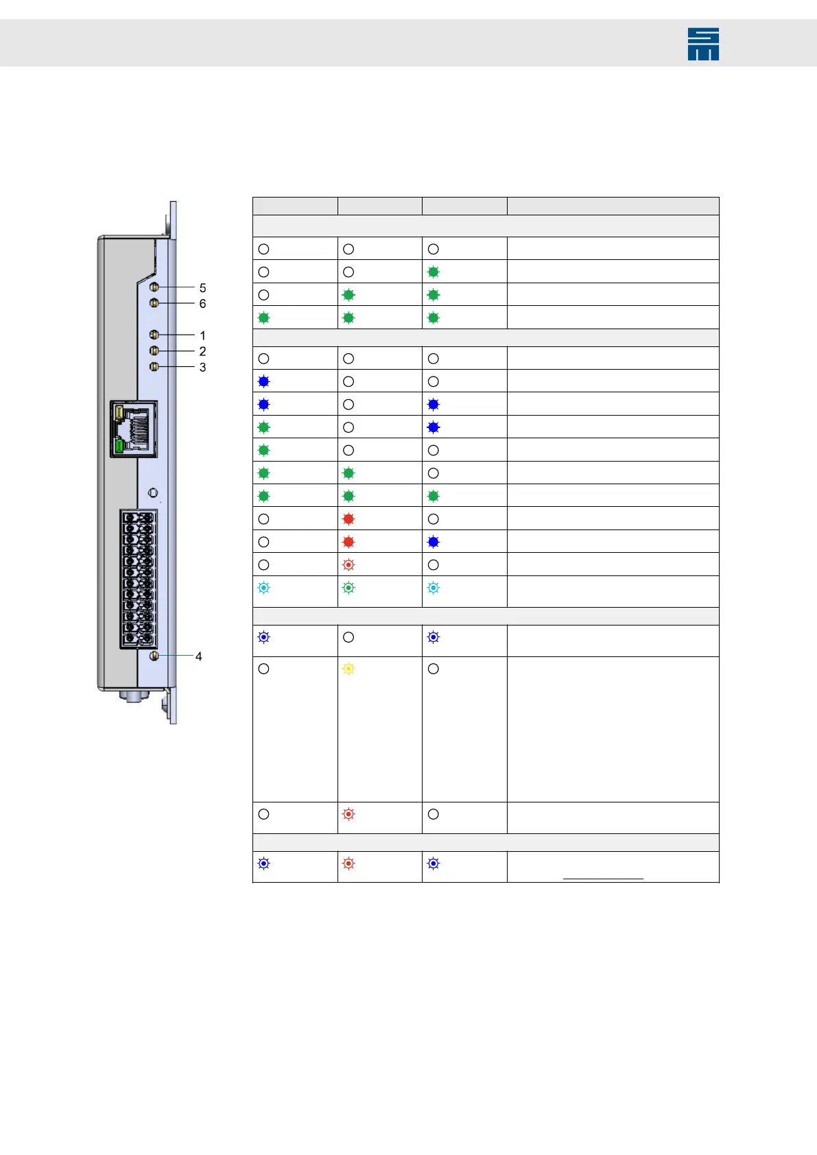
The device provides three RGB LEDs for the device status (1, 2, 3) and three RGB LEDs
for the fieldbus status (4, 5, 6). Not all colors are used.
Fig. 35: LEDs
Fig. 35: LEDs
LED 1 LED 2 LED 3 Device status
Bootloader LED sequence
(1)
Off Off Off
Bootloader active: step 1
Off Off
Green
Bootloader active: step 2
Off
Green Green
Bootloader active: step 3
Green Green Green
Bootloader active: step 4
Operational state
Off Off Off
CPU is not running
Blue
Off Off
Not ready to switch on
Blue
Off
Blue
Switch on disabled
Green
Off
Blue
Quick stop
Green
Off Off
Ready to switch on
Green Green
Off
Switched on
Green Green Green
Operation enabled
Off
Red
Off
Fault
Off
Red Blue
Fault reaction active
Off
Red fl.
Off
Unknown status
Turquoise fl. Green fl. Turquoise fl.
Device identification by drivemaster4 soft-
ware
IP address mode
Blue fl.
Off
Blue fl.
P2P button pushed for longer than 1 sec-
ond
Off
Yellow fl.
Off
Display of active IP address mode af-
ter system start and after briefly pushing
(<0.8 seconds) the P2P button
Count the number of times LED 2 flashes
yellow:
1 ×: (0) Automated (DHCP client)
2 ×: (1) Static or (2) Static + address se-
lection switch
3 ×: (3) Point to point (DHCP server)
4 ×: (4) Point to point (AutoIP)
Off
Red fl.
Off
DHCP mode cancelled, another DHCP
server was found
CPU error
Blue fl. Red fl. Blue fl.
CPU exception: CPU error announce-
ment (see Appendix (p. 64))
(1)
Green LED sequence when the bootloader mode of the drive is active (e.g. during system
software update): The steps 1 to 4 are repeated until the bootloader is exited.
Fieldbus LEDs 4, 5 and 6
The fieldbus LED 4 indicates the status of the CAN bus interface. For the real-time Eth-
ernet connection, the communication LED COM 0 (LED 5) indicates the system status
and COM 1 (LED 6) possible error states.
In the following you find the LED status descriptions depending on the fieldbus protocol.
56 Drive Amplifier SD4B - Hardware Description