Functional Safety
DANGER
Danger due to electric shock
The restart lock does not galvanically separate the output stages from the
motor. Thus, the restart lock does not protect against electric shock.
→ The complete machine must always be galvanically separated from
the mains by use of the main switch(DIN EN 60204-1 5.3) for any in-
terruptions of the operation, maintenance, repair or cleaning work at
the machine or system.
Note
All mounting locations for safety devices of the control system as well as components
mounted outside have to correspond to an IP Code IP54, if mounted correctly.
8.1.1 Functional Description of the Restart Lock
The restart lock disables the respective drive of an installation. All other drive modules
(servo amplifiers / frequency converters) remain ready for operation.
A TÜV approved safety circuit accesses relevant control units of the output stage tran-
sistors of the drive to be locked by interrupting the voltage supply of the control units.
Thus, no control pulses can be passed on to the transistors of the output stages and the
motor is at a secure standstill.
OSSD (output signal switching device)
Definition: Part of the electro-sensitive protective equipment (ESPE), which is con-
nected with the machine control and switches into the OFF state, when the sensor unit
is triggered during the intended operation (source DIN EN IEC 61496-1).
The OSSD signal is a pulsed signal, of which the phase position is shifted in relation to
the different channels. All error can be detected by checking the pulse pattern, short-
circuit for supply, cross-circuit or defect of the device. This ensures a very high safety
level (SIL 4).
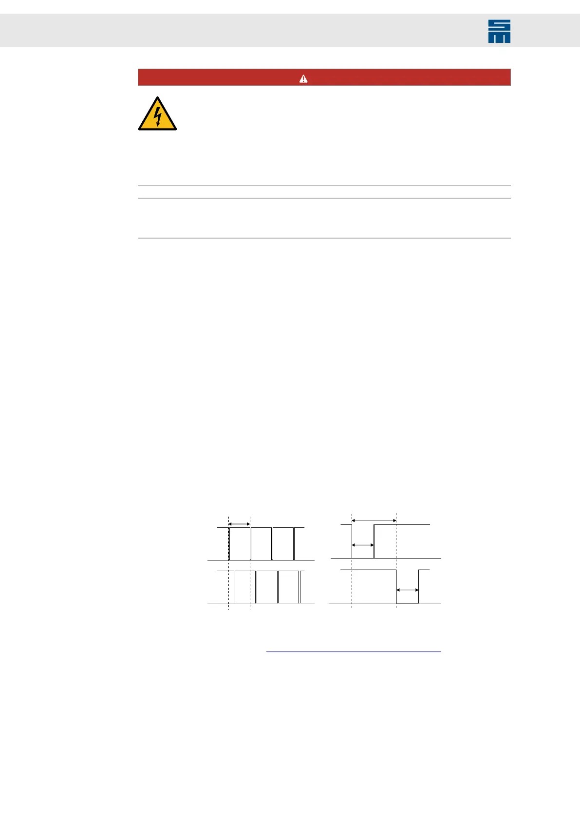
Fig. 30: OSSD Signals
OSSD test frequency OSSD test pulse width
max
1 ms
OS S D 1
min
120 ms
OS S D 1
OS S D 2
≥ 2 ms
≥
Fig. 30: OSSD Signals
The safety circuit is controlled by the OSSD1+2 signal or via one or several emergency
stop switch devices. see also chapter 8.1.2 “Wiring Example”, page 51.
If the OSSD signals or at least one of the +24 V conductors fail, the safety circuit
switches the pulse pattern of the output stage control sectors off. The response time of
the restart lock is max. 4 ms.
The restart lock must only be controlled when
▶ the drive is at a secure standstill (stop category 2),
▶ the higher-ranking control has deactivated the drive module,
▶ (reference speed value 0)
50 Drive Amplifier SD4B - Hardware Description