▶ the holding brake of the motor has been arrested.
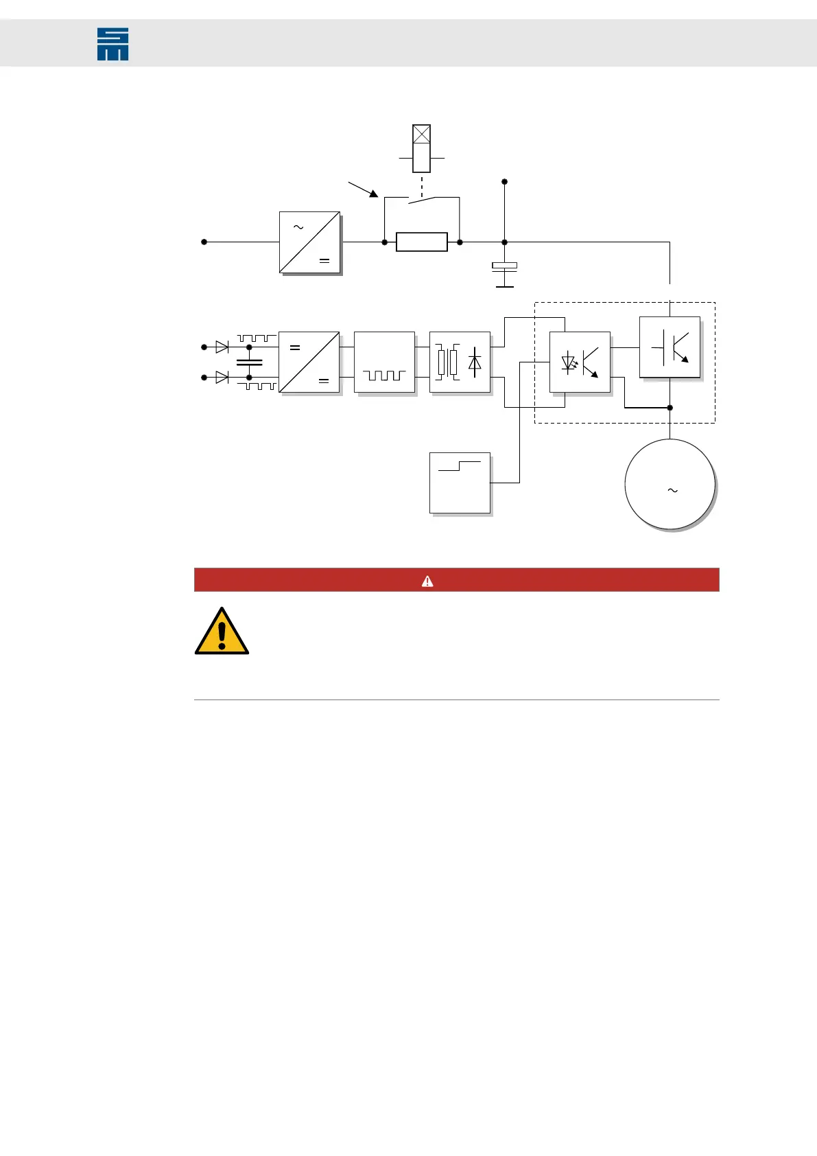
Fig. 31: Safety circuit control
Output stage sectors T1 to T6
OSC
+
-
OSSD1 / SAFE A
OSSD2 / SAFE B
Clock
On
Off
Control logic
+
3
Mains connection
Load circuit
DC +
3
M
Fig. 31: Safety circuit control
DANGER
No torque when restart lock is active
The motor cannot provide a torque when the restart lock is activated. Thus
non-self-locking drives could be released.
→ Non-self-locking drives as hanging loads must be blocked with a me-
chanical brake.
8.1.2 Wiring Example
Combining a safe emergency stop command device with an OSSD safety relay or a light
barrier with OSSD outputs and the safe switching off of the pulse patterns allows the cre-
ation of an error detection circuit, which achieves a safe stop (according to stop func-
tion category 0+1) according to the safety requirements of SIL 3 (DIN EN ISO 13849-1).
With this circuit you can connect several emergency stop devices in series, which are
permanently monitored.
51Drive Amplifier SD4B - Hardware Description
Functional Safety