7.7 X13/X14 – Fieldbus IN/OUT
Fieldbus extension for the connection of a PLC (no retrofit possible)
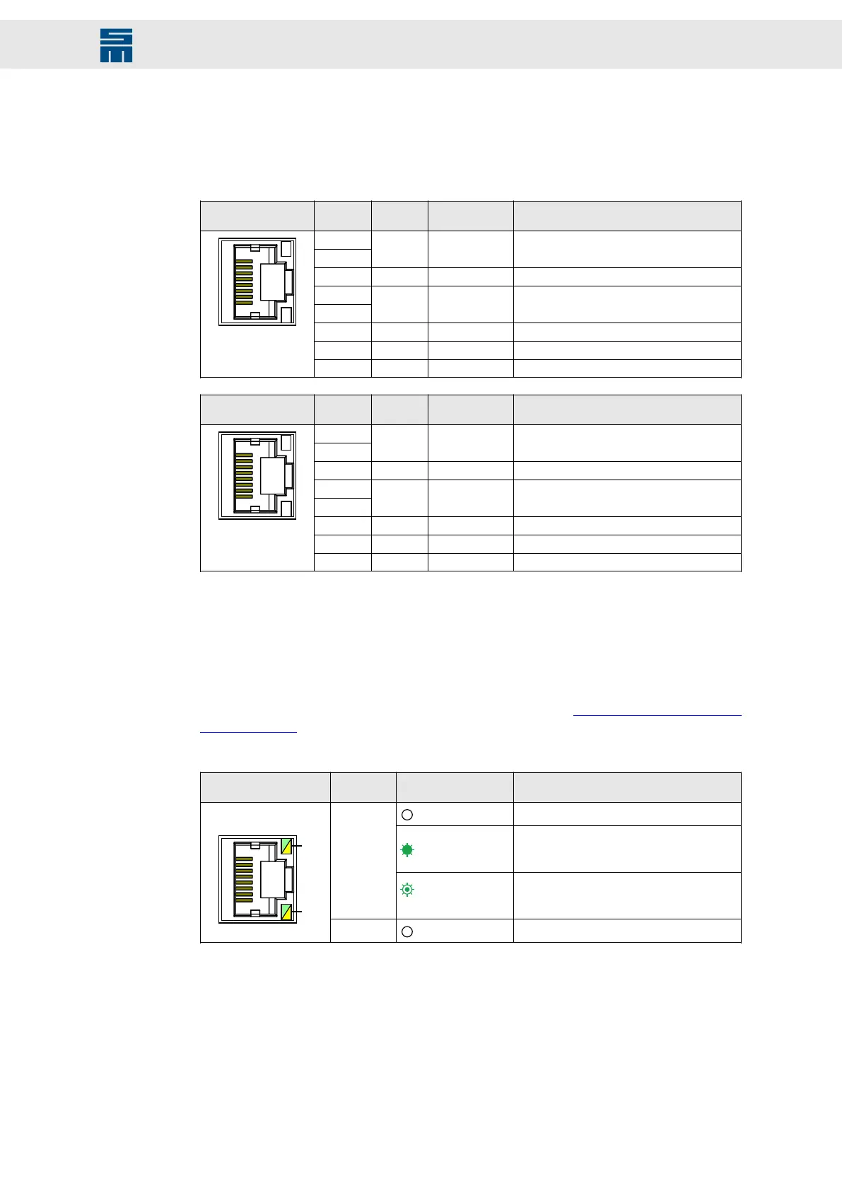
2 × 8-pole female RJ45 connector, shielded
X13 IN
Pin /
LED
I/O Name/Color Meaning
8
7
I/O VC− PoE (NC)
6 I RX− Receive data −
5
4
I/O VC+ PoE (NC)
3 I RX+ Receive data +
2 O TX− Transmit data −
1 O TX+ Transmit data +
X14 OUT
Pin /
LED
I/O Name/Color Meaning
8
7
I/O VC− PoE (NC)
6 I RX− Receive data −
5
4
I/O VC+ PoE (NC)
3 I RX+ Receive data +
2 O TX− Transmit data −
1 O TX+ Transmit data +
The fieldbus interface can be delivered with various optional Ethernet real-time proto-
cols.
LED states
The status of the real-time Ethernet connection is indicated via the LEDs at the female
RJ45 connectors and depend on the bus protocol.
For a description of the fieldbus LEDs at the device refer to chapter 9 “LED Status Dis-
plays”, page 56.
EtherCAT:
Female RJ45
connectors
LED Status Meaning
Off
No connection
Green
Link: The device has established a con-
nection with Ethernet, but does not send/re-
ceive Ethernet frames.
LED 0
Flickers green
(load-dependent)
Activity: The device has established a con-
nection with Ethernet and sends/receives
Ethernet frames.
X13 / X14
LED 1
Off
This LED is not used.
41Drive Amplifier SD4B - Hardware Description
Connectors