Functional Safety
8.1.4 Restart Lock Procedure
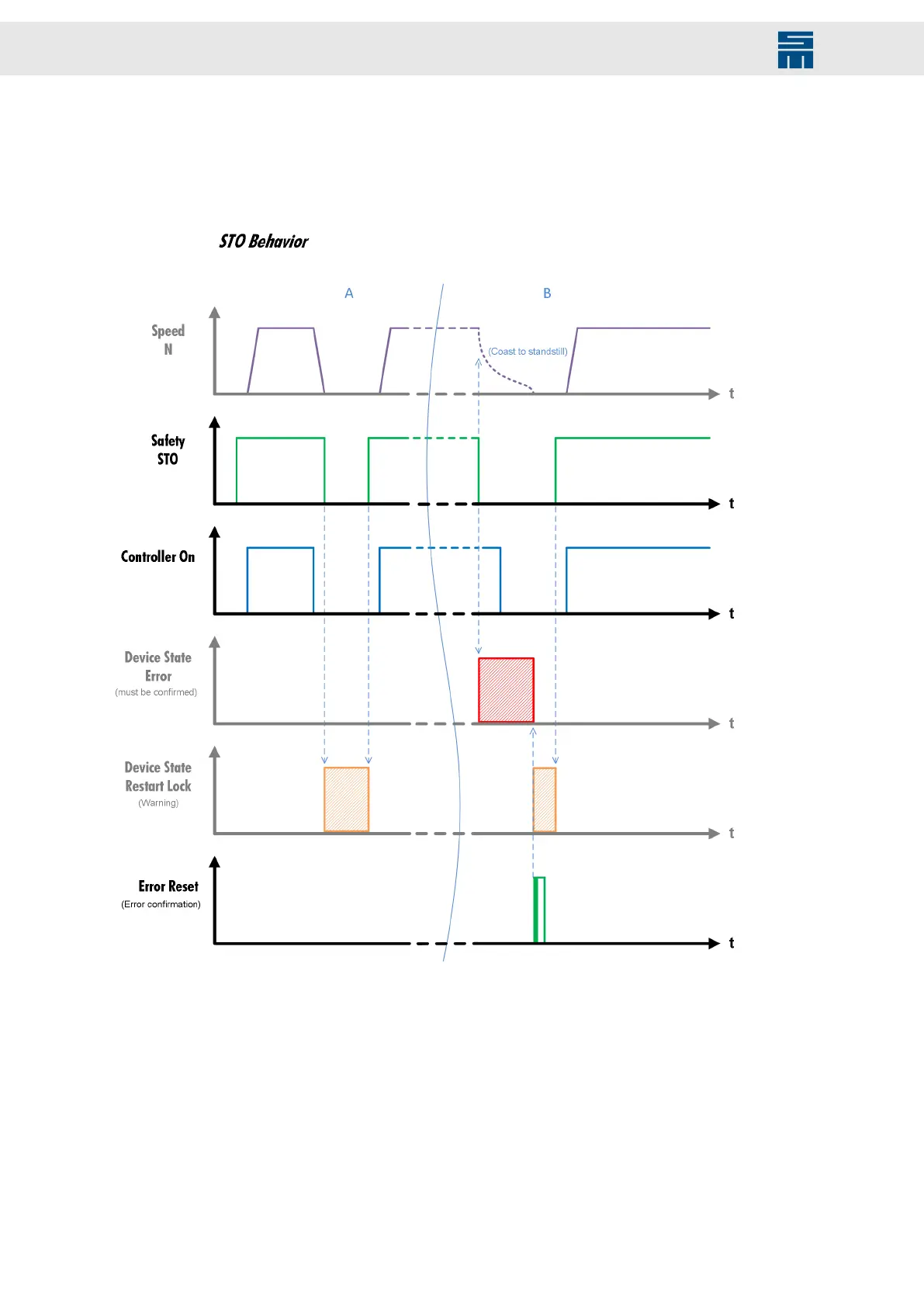
The following diagram shows the restart lock procedure by means of a time axis, includ-
ing the required steps that must be performed in order to be able to restart the device
after an activated restart lock.
Fig. 34: Behavior STO / restart lock - timing and required actions
Fig. 34: Behavior STO / restart lock - timing and required actions
Use case A If the safety function STO is activated with the power output stage switched off, the
drive amplifier cannot apply torque to a connected motor. The drive amplifier switch-
es to the status “switch on disabled”. The drive amplifier can apply torque to a con-
nected motor as soon as the safety function STO is deactivated and the power out-
put stage is switched on.
Use case B If the safety function STO is activated with the power output stage switched on, the
power output stage will be switched off and the drive amplifier cannot apply torque to
a connected motor. The drive amplifier switches to the status “fault”. The drive am-
plifier can apply torque to a connected motor as soon as the fault is acknowledged,
the safety function STO is deactivated and the power output stage is switched on.
54 Drive Amplifier SD4B - Hardware Description