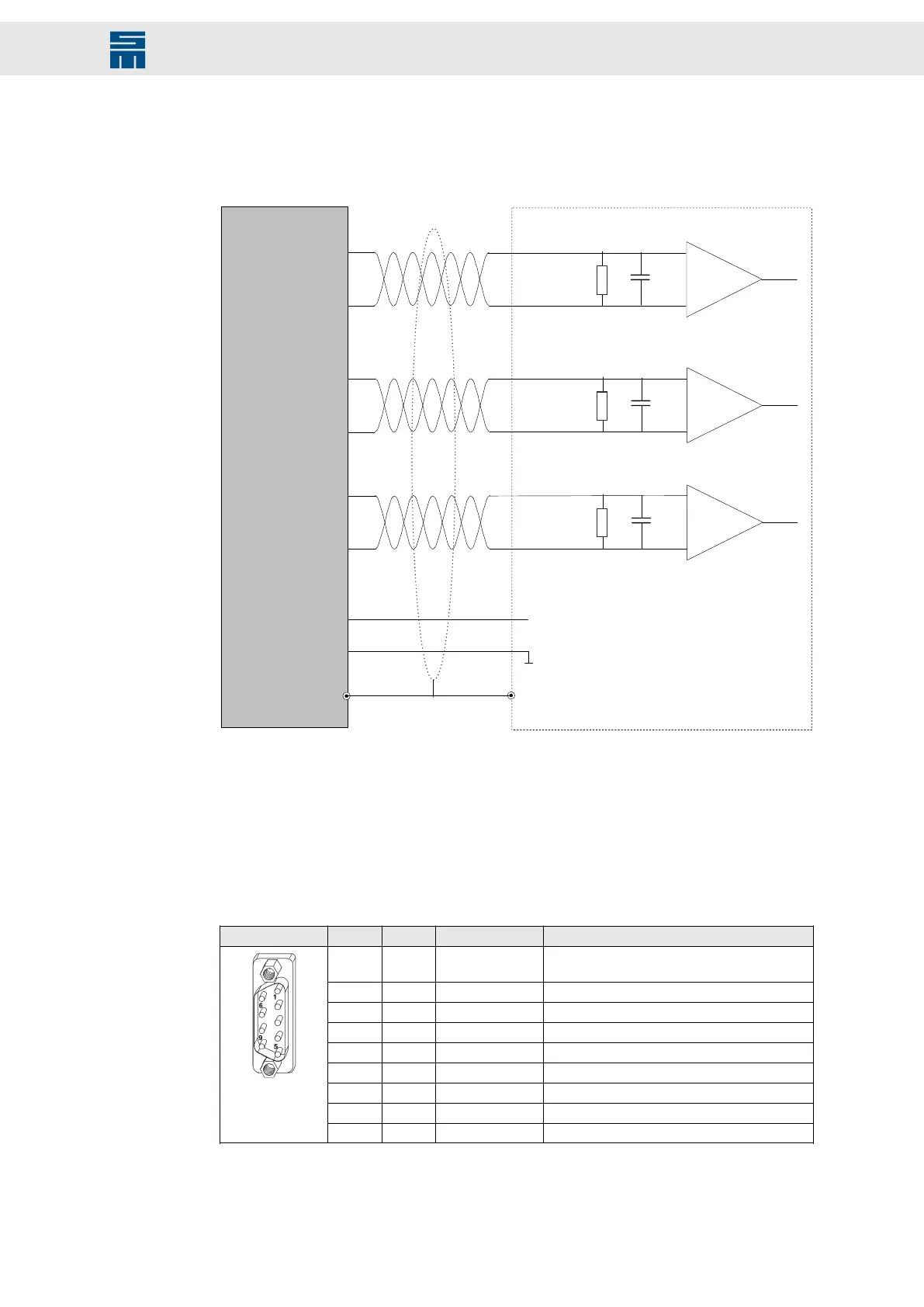
7.4.4 Incremental Encoder with TTL Signals
The connection is implemented according to interface standard EIA-422.
Fig. 15: Incremental encoder with TTL signals (X6)
+
−
UA-
UB+
UB-
2
120 Ω
V
MEAS
GND
0V / GND
M1/2 N+
M1/2 −N
Motor encoder
Drive
UA+
1
6
7
3
4
8
5
120 Ω
120 Ω
VCC5.3
M1/2 A+
M1/2 A−
M1/2 B+
M1/2 −B
UN+
UN-
+
−
+
−
l
ll
l
l
l
l
l
ll
l
l
l
¡
Fig. 15: Incremental encoder with TTL signals (X6)
7.5 X10 – Communication RS232/RS485/CAN
COM interface for the connection of the operating terminal and for CANopen and Mod-
bus RTU networks
9-pole male D-sub connector
X10 Pin I/O Name Meaning
1 O VCC5.3 5.3 V supply voltage
(power supply for optional operating terminal)
2 I RS232_Rx Receive data
3 O RS232_Tx Transmit data
4 I/O CAN_L CAN Low
5 I/O GND Ground
6 I/O RS485_D+ Data+
7 I/O RS485_D− Data−
8 I/O CAN_H CAN High
9 I/O GND Ground
Stud bolt flange: max. tightening torque = 0.7 Nm
37Drive Amplifier SD4B - Hardware Description
Connectors