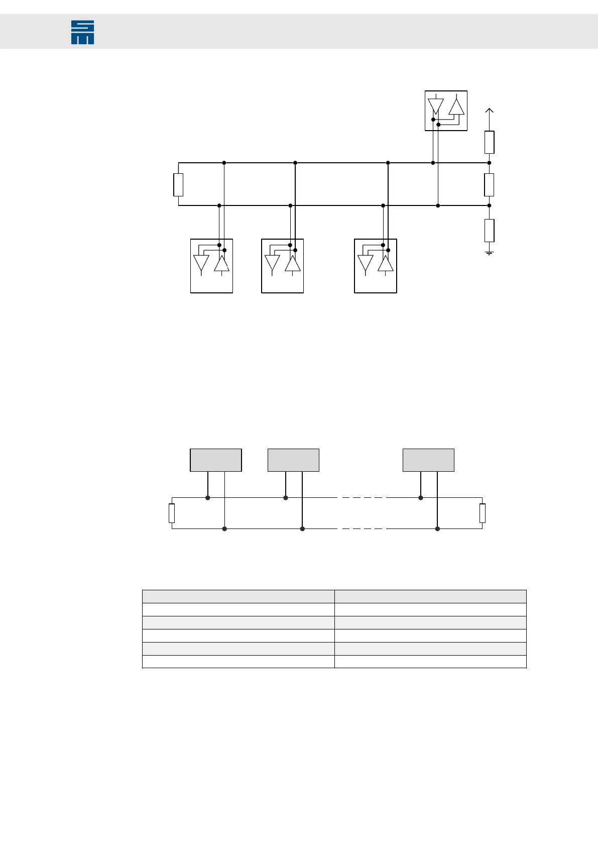
Fig. 18: RS485 bus
T
R
T
R
T
R
T
R
120 Ω
120 Ω
560 Ω
560 Ω
Master
Slave 1 Slave 2 Slave n
SD4x (X10) SD4x (X10)
SD4x (X10)
67 6767
Fig. 18: RS485 bus
7.5.3 CAN interface
The CAN interface is designed according to ISO 11898. It is a two-wire connection with
differential signals. ISO 11898 specifies a bus cable with two signal lines, CAN_H and
CAN_L. The lines have a rated impedance of 120 Ohm. The signal lines are connected
to a terminating resistor (120 Ohm) at both ends of the bus cable (see figure).
Fig. 19: CAN interface
Fig. 19: CAN interface
The total length of the bus cable must not exceed the specified lengths. The following
table indicates physical limitations valid for specific transmission rates:
Baud rate Max. bus length
50 kBd 1000 m
125 kBd 500 m
250 kBd 250 m
500 kBd 100 m
1000 kBd 25 m
The number of bus nodes is also limited by the specification according to ISO 11898.
The limiting value is between 32 and 100 bus nodes depending on the used cable and
transmission rate. For further information on the maximum number of bus nodes refer to
the document “CAN Physical Layer” by the user organization CiA.
39Drive Amplifier SD4B - Hardware Description
Connectors