7.9.1 Connecting the Voltage Supply
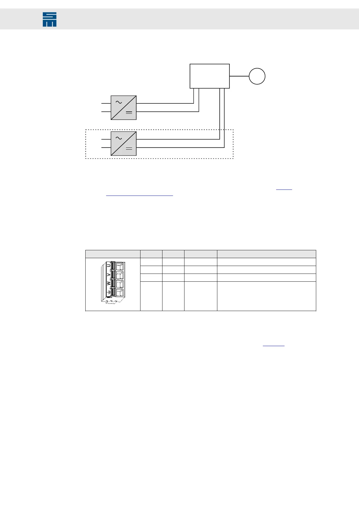
Fig. 28: DC power supply connection for X36 and X15
230 V
AC
M 3~
GND
24 V
DC DC
80 V–
1
X15
SD4B
X36
2 A2 A1
230 V
AC
GND
24 V
DC
(1)
Fig. 28: DC power supply connection for X36 and X15
(1)
The logic supply at X15 is required under the following conditions:
▶ maintaining the error messages after switch-off is desired
▶ higher output currents of the digital outputs (> 20 mA), see connection example chapter
7.8.2 “Digital Outputs”, page 43
7.10 X53 – Motor Connection
4-pole Combicon connector, suitable for mating connector FKCN 2,5/ 4-ST-5,08
(Phoenix)
Mating connector X53 Pin I/O Name Meaning
1 O U Motor phase U
2 O V Motor phase V
3 O W Motor phase W
4 PE Protective conductor
Specification of terminal connections
▶ Conductor cross-section solid: 1 to 1.5 mm²
▶ Conductor cross-section stranded: 1 to 2.5 mm²
▶ Connection method: push-in spring connection (handling: see page 29)
47Drive Amplifier SD4B - Hardware Description
Connectors