Set/reset operations
(continued)
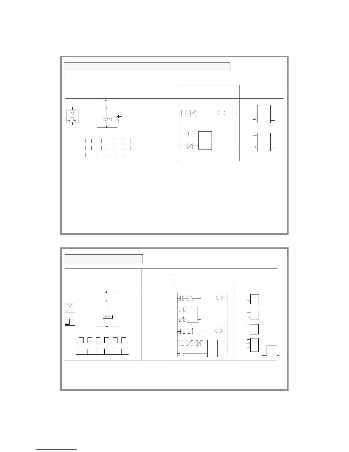
On each leading edge of the signal at input I 1.7,
the AND condition (AI 1.7 and AN F 4.0) is satisfied;
the RLO is "1". This sets flags F 4.0 (edge flag) and
F 2.0 (pulse flag).
Flag F 2.0 is reset.
In the next processing cycle, the AND condition
AI 1.7 and AN F 4.0 is not satisfied, since flag F 4.0
has already been set.
Flag F 2.0 therefore only remains "1" for one program
run.
I 1.7
F 4.0
F 2.0
I 1.7
F2.0
F4.0
I 1.7
F2.0
A
AN
=
A
S
AN
R
I 1.7
F 4.0
F 2.0
F 2.0
F 4.0
I 1.7
F 4.0
Logical/circuit diagram
STEP 5 representation
Ladder Control system
Statement
list
Simulation of a momentary contact relay (one shot)
diagram flowchart
I 1.7
F 2.0
I 1.7
F 4.0
F 2.0
F 4.0
S
RQ
&
F 2.0
I 1.7 F 4.0
S
RQ
F 4.0
F 2.0
I 1.7
I 1.0
I 1.0
A I 1.0
Q3.0
I 1.0
M1.0
M1.1
F 2.0
Q 3.0
AN F 1.0
= F 1.1
F 1.1A
F 1.0S
I 1.0AN
F 1.0R
A F 1.1
A Q3.0
= F 2.0
A F 1.1
AN Q3.0
Q 3.0S
AN F 2.0
A F 2.0
R Q 3.0
The binary scaler (output Q 3.2) changes its state
to 1 (leading edge). Therefore, only half the input
frequency appears at the output of the memory cell.
each time input I 1.0 changes its signal state from 0
F1.1 Q3.0
F 2.0
S
RQ
F1.1
I1.0
F1.0
I1.0 F1.0
F1.1
S
RQ
F1.1
Q3.0
F2.0
Q3.0
F2.0
0
&
I1.0
F1.0
&
F1.1
F1.1
I1.0
S
F1.0
RQ
F1.1
Q3.0
F2.0
F2.0
Q3.0
S
RQ
F1.1
Q3.0
&
F2.0
Q 3.0
Logical/circuit diagram
STEP 5 representation
Ladder Control system
Statement
list
Binary scaler (binary divider)
diagram flowchart
Programming Examples in the STL, LAD and CSF Methods of Representation
CPU 948 Programming Guide
C79000-G8576-C848-04
3 - 39