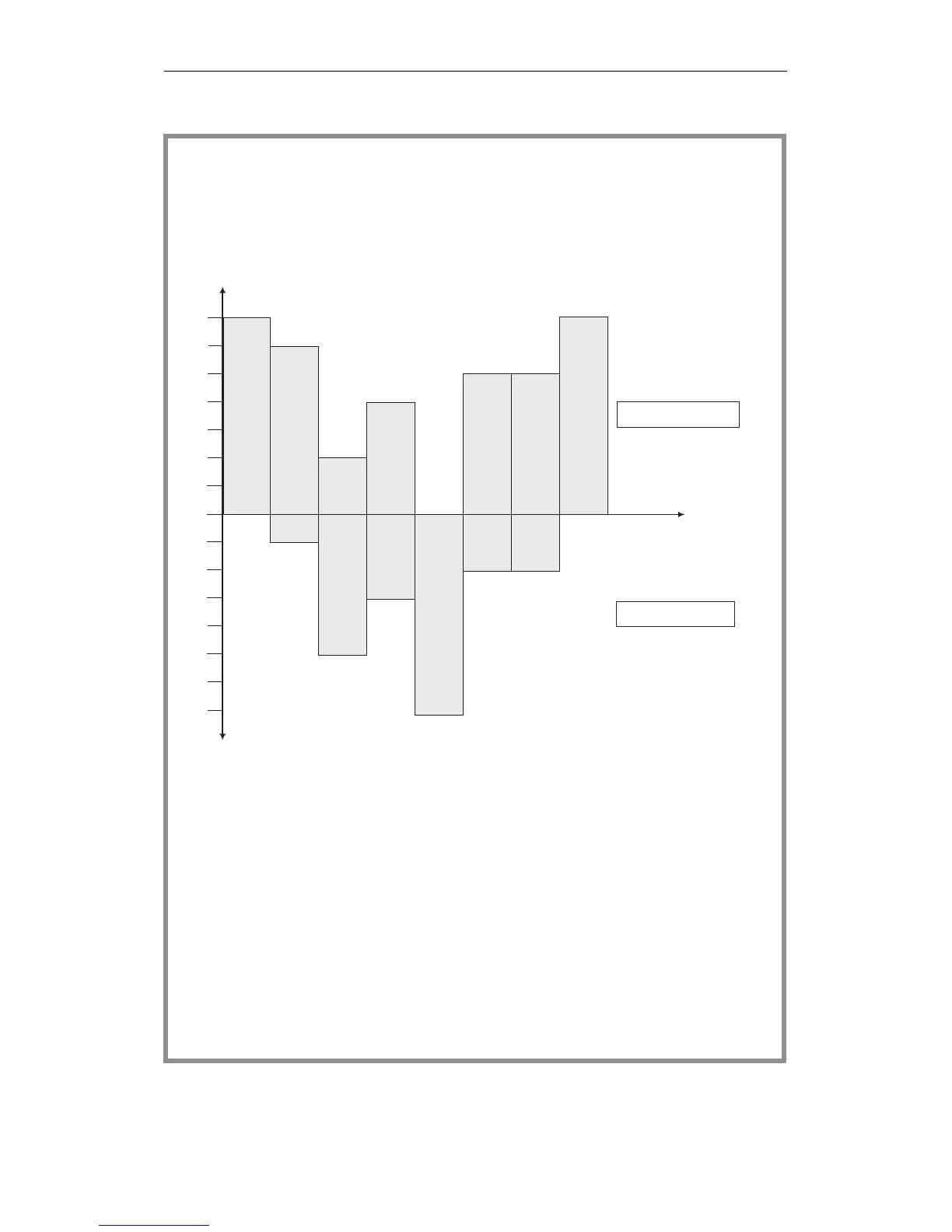
Example
Occupation of the buffer by a link
The link between CPU 3 and CPU 2 is initialized. The link is assigned seven
memory fields in the buffer of the coordinator. Following this, the data
transfer shown below would be possible.
Sending/receiving n data fields means that the corresponding functions are
called n times one after the other.
To simplify the representation, at any one time, data can either be sent or
received in this example.
It is, however, possible and useful to transmit (CPU 3) and receive (CPU 2)
simultaneously ("Parallel processing in a multiprocessor programmable
controller"). In the example, fields H and I are received while fields K
and L are sent.
The example illustrates the queue organization of the buffer: the fields of
data sent first (A,B,C...) are received first (A,B,C...).
7
7
6
6
5
5
4
4
3
3
2
2
1
1
0
Transmitter: CPU 3
initialize
0
0
send
field A
send 4 fields
B, C, D, E
send 4 fields
F, G , H , I
send 2 fields
K, L
Time
receive
fields A, B
receive
fields C, D,
E, F, G
receive
fields H, I
receive
fields K, L
Transmitting capacity
(no. of free
memory fields)
Receiving capacity
(no. of free
memory fields)
6
2
5
7
7
1
4
3
7
2
2
5
5
Receiver: CPU 2
Fig. 10-5 Example of the occupation of the COR buffer
Multiprocessor Communication
CPU 948 Programming Guide
C79000-G8576-C848-04
10 - 19