Within a sequence of logic operations, the RLO is formed from the type
of operation, previous RLO and the scanned signal state. A sequence of
logic operations is completed by an operation (e.g. set/reset operations)
which retains the RLO (
ERAB = 0). Following this, the RLO can be
evaluated but cannot be further combined.
Example
Set/reset operations
Operation Operand Function
S
R
I 0.0 to 127.7
Q 0.0 to 127.7
F 0.0 to 255.7
S 0.0 to 4095.7
D 0.0 to 255.15
Set if RLO = 1
Reset if RLO = 1
an input in the PII
an output in the PIQ
a flag
an S flag
a bit in the data word
=
I 0.0 to 127.7
Q 0.0 to 127.7
F 0.0 to 255.7
S 0.0 to 4095.7
D 0.0 to 255.15
The RLO is assigned to
an input in the PII
an output in the PIQ
a flag
an S flag
a bit in the data word
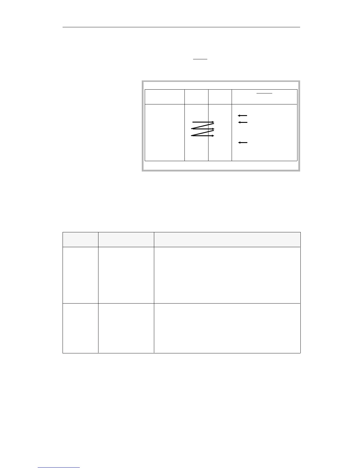
Program Status RLO ERAB
:
=Q0.0
AI1.0
AI1.1
AI1.2
=Q0.1
0
1
1
0
0
0
1
1
0
0
0 RLO retained
1 first bit scan
1
1
0 RLO retained, end of
the logic operations
sequence
Table 3-3 Set/reset operations
Basic Operations
CPU 948 Programming Guide
3 - 20 C79000-G8576-C848-04