Hardware interfaces
Version 8 dated 15.03.00 16
Siemens Information and Communication Products
A
4 Hardware interfaces
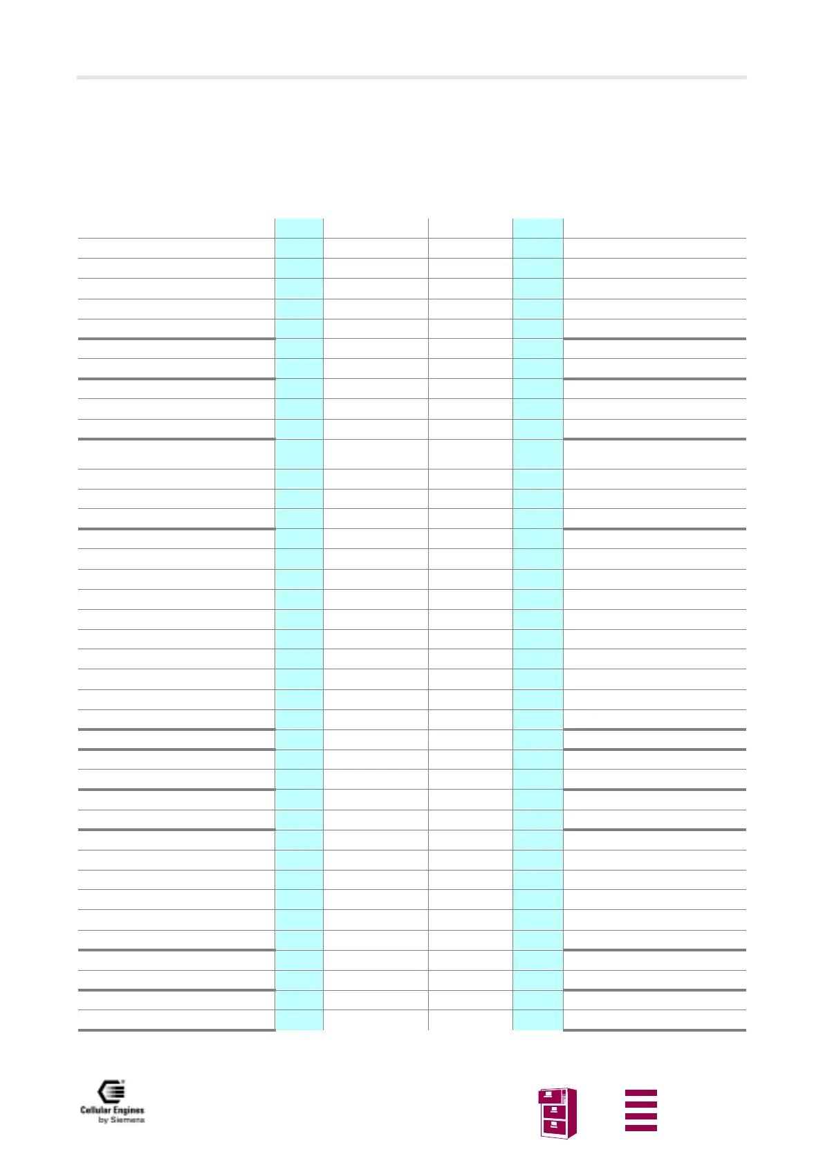
4.1 Pin assignment of the 80-pole SMD connector
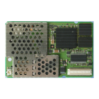
The location of PIN 1 is shown in “Design drawing of the M20”.
Site on PCB
Table 4-1 Pin assignment of the 80-pole SMD connector
Parallel display data bus Pin 1
D14 D15
Pin 80 Parallel display data bus
Parallel display data bus Pin 2
D12 D13
Pin 79 Parallel display data bus
Parallel display data bus
Pin 3
D10 D11
Pin 78 Parallel display data bus
Parallel display data bus
Pin 4
D8 D9
Pin 77 Parallel display data bus
Parallel display data enable
Pin 5
DE DRS
Pin 76 Parallel display address (A0)
Parallel display write
Pin 6
HWR# DCS#
Pin 75 Parallel display chip select
Reset
Pin 7
RES# POWER_ON
Pin 74 Power on indication
Ignition Pin 8
IGNITION USCRTS
Pin 73 Request to send
Clear to send
Pin 9
USCCTS USCTX
Pin 72 Transmit data
Receive data
Pin 10
USCRX RXDATA
Pin 71 2. serial interface receive data
Ring indication
Pin 11
USCRI TXDATA
Pin 70 2. serial interface transmit data
VSB to/from controller
Synchronisation
Pin 12
VSFS_C VSFS_V
Pin 69 VSB to/from codec
Synchronisation
VSB to/from controller clock
Pin 13
VSCLK_C VSCLK_V
Pin 68 VSB to/from codec clock
VSB to/from controller data input
Pin 14
VSDI_C VSDO_V
Pin 67 VSB to/from codec data output
VSB to/from controller data output
Pin 15
VSDO_C VSDI_V
Pin 66 VSB to/from codec data input
Data terminal ready Pin 16
DTR GND Pin 65
Ground
Ground
Pin 17 GND GND Pin 64
Ground
6 V Power supply
Pin 18 DC_IN GND Pin 63
Ground
6 V Power supply
Pin 19 DC_IN DC_IN Pin 62
6 V Power supply
6 V Power supply
Pin 20 DC_IN DC_IN Pin 61
6 V Power supply
6 V Power supply
Pin 21 DC_IN DC_IN Pin 60
6 V Power supply
6 V Power supply
Pin 22 DC_IN DC_IN Pin 59
6 V Power supply
Ground
Pin 23 GND DC_IN Pin 58
6 V Power supply
Ground
Pin 24 GND GND Pin 57
Ground
Ground
Pin 25 GND GND Pin 56
Ground
Data set ready
Pin 26
DSR CCCLK
Pin 55 SIM card clock
SIM card reset
Pin 27
CCRST DCD
Pin 54 Data carrier detect
SIM card data
Pin 28
CCIO CCIN
Pin 53 SIM card inserted
Reserved pin Pin 29
GPCS CCVCC
Pin 52 SIM card supply
Download enable
Pin 30
BOOTCODEEN GPIO1
Pin 51 Battery load indicator
not connected
Pin 31 NC GPIO0
Pin 50 Supply source indicator
Keypad column 2
Pin 32
KPC2 KPC3
Pin 49 Keypad column 3
Keypad column 0
Pin 33
KPC0 KPC1
Pin 48 Keypad column 1
Keypad row 4
Pin 34
KPR4 KPR5
Pin 47 Keypad row 5
Keypad row 2 Pin 35
KPR2 KPR3
Pin 46 Keypad row 3
Keypad row 0
Pin 36
KPR0 KPR1
Pin 45 Keypad row 1
Hookswitch
Pin 37
HOOKSW BUZZER
Pin 44 Buzzer
Ground
Pin 38
GND GND
Pin 43 Ground
Microphone minus
Pin 39
MICN MICP
Pin 42 Microphone plus
Speaker minus
Pin 40
SPN SPP
Pin 41 Speaker plus
 Loading...