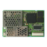
Hardware interfaces
Version 8 dated 15.03.00 17
Siemens Information and Communication Products
A
The interfaces are described in detail in Chapters 4.2 “Power supply” on page 17, 4.3 “Interfaces on the 80-pole SMD connector”
on page 17
and 4.4 “Audio interface” on page 25.
Note
: Unused pins
• In all cases in which the DAI is not used, the voiceband serial connector to/from controller has to be connected
externally to the voiceband serial connector to/from codec. Connection wires should be as short as possible (10
cm maximum)
Connect VSFS_V to VSFS_C, VSCLK_V to VSCLK_C, VSDO_V to VSDI_C, VSDI_V to VSDO_C. For ad-
ditional information, see also Chapter
8.8.5 “Adding echo suppression functionality” on page 200.
• RXDATA must be connected to RES#, if not used.
• The following pins (if unused) shall be:
connected to GND: CCIN
connected to a 10 kOhm - 100 kOhm pull-down (ground) resistor: BOOTCODEEN, GPIO0, GPIO1, HOOKSW
not connected: all display pins, all keypad pins, USCxxx, MICN, MICP, BUZZER, SPN, SPP, POWER_ON,
RES#, DSR, DCD, TXDATA, DTR, GPCS.
• All DC_IN pins and all GND pins shall be used!
• The maximum number of push-pull cycles of the SMD connector shall not exceed 100.
4.2 Power supply
Single voltage power supply: 6V +/- 0.2 V
Current consumption: max. 2A pulses.
Switch-in current pulse I
max
= 15 A, duration: approx. 10 µs,
(when voltage is applied) decreasing (1/e) time constant <90 µs at R
supply
<0.1Ω
decreasing time to stand-by current value: < 300 µs
Stand-by state I
≤ 0.2 mA
(voltage is applied, ignition not yet asserted)
Idle mode I < 20 mA average
typ. 14 mA average (depends on network operator)
Call in progress I < 2A (pulsed t = 577 µs at T = 4.615 ms)
typ. 1.5 A for performance class 5
arithmetic mean: I < 250 mA
4.3 Interfaces on the 80-pole SMD connector
This chapter describes all interfaces (except power supply) on the 80-pole SMD connector.
4.3.1 Specification of 2.8 V logic level
The following diagram shows the 2.8 V logic level specification used in the M20:
Table 4-2 2.8 V logic level specification
Parameter Min. Max.
Vo
H
output high voltage 2.3 V 2.9 V
Vo
L
output low voltage 0 V 0.4 V
Vi
H
input high voltage 2.1 V 3 V
Vi
L
input low voltage -0.3 V 0.8 V
 Loading...