Hardware interfaces
Version 8 dated 15.03.00 26
Siemens Information and Communication Products
A
4.5 Antenna interface
The antenna must satisfy the following electrical requirements:
In principle, the GSM antenna is selected by the manufacturer of the base unit. The GSM antenna may be mounted directly
or via cable, depending on the application and the RF field at the local site.
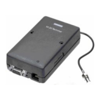
The antenna interface connector of the M20 unit is SMR nano (male). Hence, the connector on the GSM antenna or
antenna cable has to be SMR nano (female).
Note
: the maximum number of push/pull cycles shall not exceed 100.
For further information on GSM antennas and sources of connectors, see Chapters
7.1 “GSM antenna” on page 154 and 7.5
“Sources for connectors” on page 157
.
Frequency, TX 890-915 MHz
Frequency, RX 935-960 MHz
Impedance 50 Ω
VSWR TX: max. 1.7:1 installed
RX: max. 1.9:1 installed
Gain > 1.5dB referenced to λ/2 dipole
3dB width of cone vertical: 80°
horizontal: 360°
Maximum power 1W (cw), 2W peak; at ambient temperature of 55°C

 Loading...


