Hardware interfaces
Version 8 dated 15.03.00 18
Siemens Information and Communication Products
A
4.3.2 Power on/off
Note:
1
) Level range: 0 < IGNITION < 6.2 V, (maximum voltage: +/-50 V). For additional information see 8.8.6 “Ignition line”
on page 200
.
2
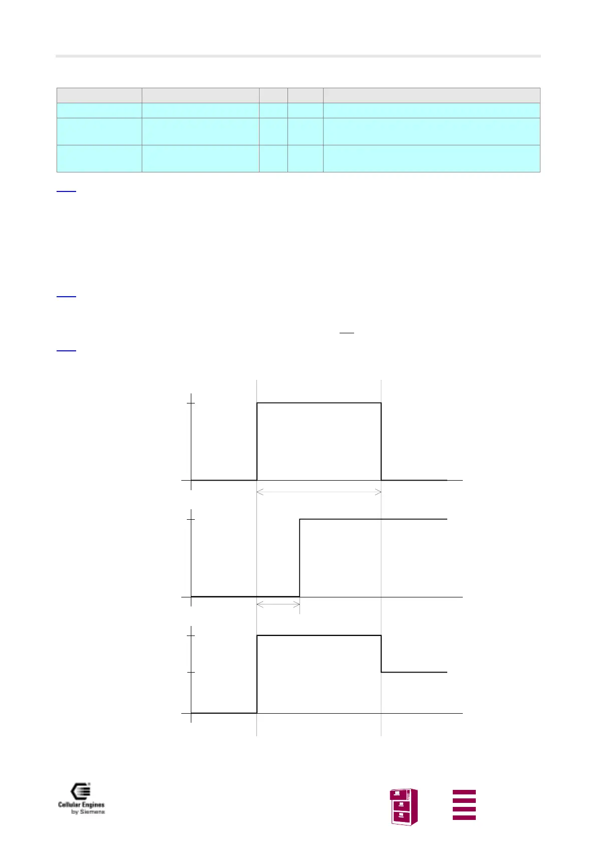
) See Fig. 4-1 Timing of power on/off signals case IGNITION > 2.7 V level = IGNITION – 0.7 V.
To turn on the M20, connect IGNITION to the voltage specified in the table above. The device will then keep running
even if a voltage < 0.6 V is applied to IGNITION or the device is left disconnected. To turn off the M20, use the corre-
sponding AT command (AT^SMSO, see Chapter
5.7 “Siemens-defined AT commands for enhanced functions” on page 111).
Note
: if IGNITION is connected to a fixed voltage > 1.3 V, the M20 cannot be turned off with an AT command.
POWER_ON indicates that the microprocessor of M20 is supplied.
RES# level High indicates that the microprocessor of M20 is supplied and
working.
Note
: RES# also can be used as 2.8 V reference level for applications of the M20.
For additional information, see
Fig. 4-1 Timing of power on/off signals.
Fig. 4-1 Timing of power on/off signals
Signal Function I/O Level Comments
IGNITION Switch on I
1
) IGNITION >2.7 V for longer than 1 s switches on
POWER_ON Power-on indicator O
2
) Load current < 300 uA
Note: may be unconnected if unused
RES# Reset indicator O 2.8V Load current < 500 uA
Note: may be unconnected if unused
Uswitchon
IGNITION
t
2.8V
RES#
t
Uswitchon-0.7V
POWER_ON
t
2V typ.
300ms
duration > 1s
 Loading...