Hardware interfaces
Version 8 dated 15.03.00 20
Siemens Information and Communication Products
A
Table 4-3 Timing values of display interface
4.3.4 Keypad
10 Pins for 4*6 keypad matrix.
For activation of a key, connect a row signal to the appropriate column signal. The keypad address matrix implemented
in the MMI software can be found in Chapter
6.2 “Keypad address matrix” on page 142.
Note
: maximum input speed: 1 key per 400ms
4.3.5 Serial Interface RS323 (V.24) Connections and signals
The Serial Interface can be used for:
• AT command interface
• Software download (SW update), see
8.5 “SW download (Version update)” on page 191
• serial interface for data/fax/SMS services.
Note
:
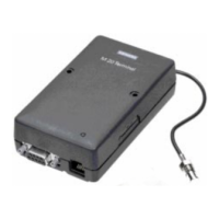
External level converter is necessary for V.24 level when using the M20.
The M20T has a direct 9 pin serial interface port.
Parameter Comment Min. Typ. Max. Units
t
10
Write high byte to display enable high 152 ns
t
11
Display enable high width 462 ns
t
12
Display enable low width 462 ns
t
13
Display register select setup 10 ns
t
14
Display register select hold 5 ns
t
15
Display chipselect setup 10 ns
t
16
Display chipselect hold 5 ns
t
17
Data setup 68 ns
t
18
Data hold 15 ns
t
11a
Display enable high width read extension 538 ns
t
19
Display enable low to write high 10 ns
t
20
Display register select to display enable high 200 ns
t
21
Display chipselect to display enable high 200 ns
t
22
Display enable high to data valid 450 ns
t
23
Data hold 0 ns
Signal Function I/O Level Comments
KPR0...5 Keypad row I 2.8 V may be disconnected if unused
KPC0...3 Keypad column O 2.8 V may be disconnected if unused
 Loading...