Version 8 dated 15.03.00 5
Siemens Information and Communication Products
A
Figures
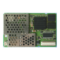
Fig. 3-1 Design of the Siemens M20 ........................................................................................9
Fig. 3-2 M20 interface diagram ..............................................................................................15
Fig. 4-1 Timing of power on/off signals .................................................................................18
Fig. 4-2 Write timing of display interface ...............................................................................19
Fig. 4-3 Read timing of display interface ...............................................................................19
Fig. 4-4 Timing characteristics of DAI to microcontroller .....................................................23
Fig. 4-5 Timing characteristics of DAI to codec ....................................................................23
Fig. 6-1 Display structure ......................................................................................................143
Fig. 7-1 Big SIM Card Reader (L04) ....................................................................................154
Fig. 7-2 Mini SIM card reader (C707-1) ...............................................................................155
Fig. 7-3 Mini SIM card reader (C707-3) ...............................................................................155
Fig. 7-4 Mini SIM card reader (holder) ................................................................................155
Fig. 7-5 Mini SIM card reader (connector) ...........................................................................155
Fig. 7-6 SMR connector (straight) ........................................................................................157
Fig. 7-7 80-pole SMD connector (rigid) ...............................................................................157
Fig. 7-8 80-pole SMD connector (floating) ..........................................................................157
Fig. 8-8 Handsfree application diagram ................................................................................ 200
Fig. 8-4 Level converter ........................................................................................................198
Fig. 8-5 Voltage supply .........................................................................................................198
Fig. 8-6 SIM card connection pins ........................................................................................199
Fig. 8-7 Handset connection .................................................................................................199
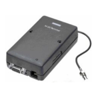
Fig. 9-1 Modular Cellular Engine Siemens M20 Terminal ..................................................202
Fig. 9-2 Front view of Western plug 6-6 (male) ................................................................... 203
Fig. 9-3 Front view of Western plug 4-4 (male) ................................................................... 204
Fig. 15-1 Design drawing of the M20 .....................................................................................213
Fig. 15-2 M20 screw dimensions ............................................................................................214
Fig. 15-3 M20 Terminal front view ........................................................................................214
Fig. 15-4 M20 Terminal back view ........................................................................................214
Fig. 15-5 M20 Terminal top and side view .............................................................................215
Fig. 15-6 M20 Terminal bottom view ..................................................................................... 216
Tables
Table 3-1 Teleservices ...............................................................................................................10
Table 3-2 Mobile station features ..............................................................................................13
Table 3-3 Supplementary mobile station features .....................................................................14
Table 4-1 Pin assignment of the 80-pole SMD connector ......................................................... 16
Table 4-2 2.8 V logic level specification ...................................................................................17
Table 4-3 Timing values of display interface ............................................................................20
Table 4-4 Timing characteristics of DAI ................................................................................... 24
Table 5-1 Standard Hayes AT commands .................................................................................29
Table 5-2 AT commands according to GSM 07.07 ................................................................... 55
Table 5-3 AT commands according to GSM 07.05 ................................................................... 94
Table 5-4 Siemens-defined AT commands .............................................................................112
Table 5-5 Summary of CMS ERRORS ...................................................................................140
Table 6-1 Keypad address matrix ............................................................................................142
Table 6-2 Description of keypad .............................................................................................142
 Loading...