52
SITRANS F M MAGFLO
DKFD.PS.027.W3.02
7. Electrical connection
E. c.
7.2
Wiring diagram for signal
converter and sensor
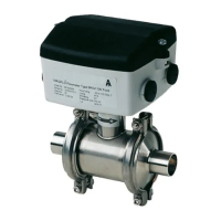
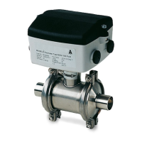
Compact installation
Compact
Remote IP 67 wall mounting
Remote installation
Cathodic protected piping
Compact installation:
The signal converter must be supplied through an isolation transformer. The terminal "PE" must
not be connected.
Remote installation:
The screen must only be connected at the sensor end via a 1.5 µF capacitor. The screen must
never be connected at both ends.
Sensor cables
• Unscreened cable ends must be as short as possible and the two cables must be kept separate.
Cables must be in one length and must not be taken to a distribution box or similar terminal
arrangement.
• Terminals 81 and 84 are only connected when special electrode cable with double screening
is used.
• Coil cable screen must be connected in both ends. Electrode cable screen must be connected
at sensor side only.
Note
See 5.3 when using cathodic protection.
Note
Mount the grounding wire from connection box to PE to ensure sufficient grounding.
 Loading...