Siemens Industry, Inc. 18 A6V12198161_en--_a
Smart Infrastructure
7. PROGRAMMING THE SCALANCE XC206-2SFP-MM
MULTIMODE AND XC206-2SFP-SM SINGLE MODE ETHERNET
FIBER SWITCH
This section describes how to assign an IP address to the Scalance XC206-2SFP-MM Multimode or
XC206-2SFP-SM Single Mode Ethernet Fiber Switch and the methods used for determining IP
addresses to assign to the switches. It also describes how to configure one of the switches as the
Redundancy Manager.
7.1 Fiber Switch Introduction
The fiber switch can be configured independently or in the network. The initial configuration of the
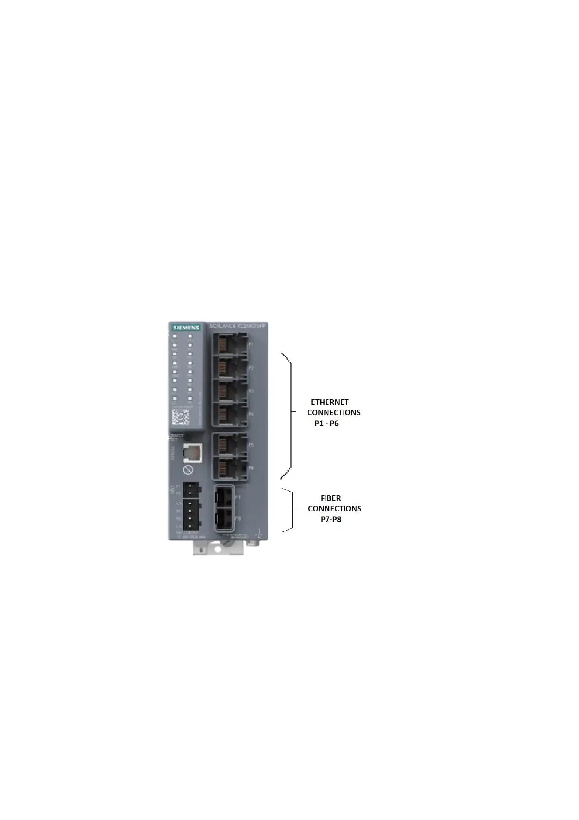
fiber switch must be made before connecting it to the system. The fiber switch has six RJ-45 jacks
(P1-P6) for Ethernet connections and two pair of fiber optic connection ports (P7-P8).
Each fiber switch must be programmed with a unique IP address. The recommended range of IP
addresses is from 192.168.1.201 to 192.168.1.250.
Figure 7–1: Scalance XC206-2SPF-MM/-SM Ethernet Fiber Switch Connections
The fiber switch is powered from the battery backed up local 24V power supply. It is monitored by
the Management Station. Configuration is made using a Primary Setup Tool (PST) and a web
browser.
 Loading...